
Cutting Tool Selection Impacts the Outcome of Hard Metal Machining
Effective cutting tools for the HSM of hardened die steel is an effective solution to a more profitable and easier machining process.


Figure 2b: The weaker tool is modified with a neck for doing straight walls.
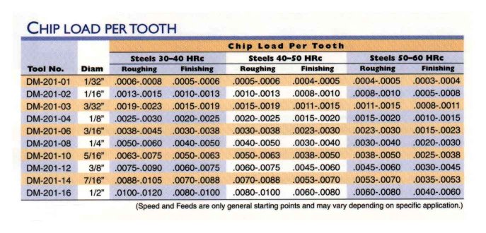
Figure 5: Recommended chip loads for ball end tools.
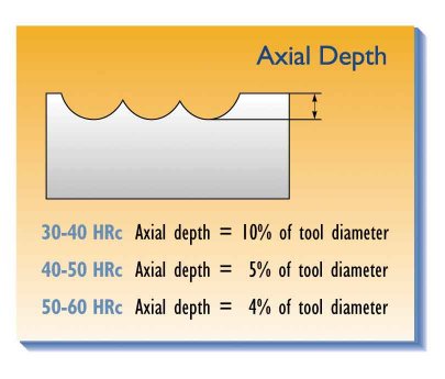
Figure 7: The axial depth is critical to the HSM process.
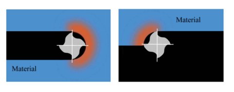
Figure 4: Heat generation at the cutting edge.
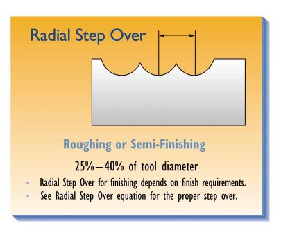
Figure 3: Radial step-over distance for roughing and semi-finishing with a ball end mill.
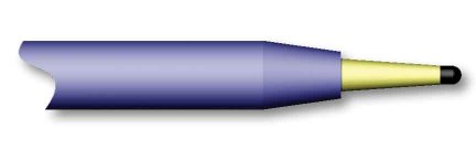
Figure 2a: The stronger tool is modified with an angled neck for clearance.
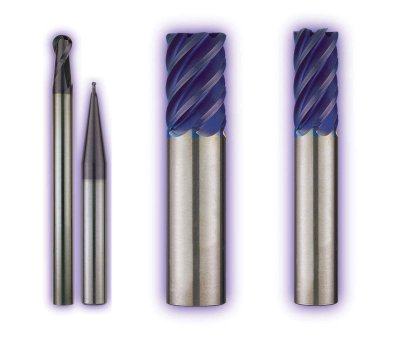
Figure 1: The three basic designs of cutters are ball end, corner radius (bullnose) and square end.
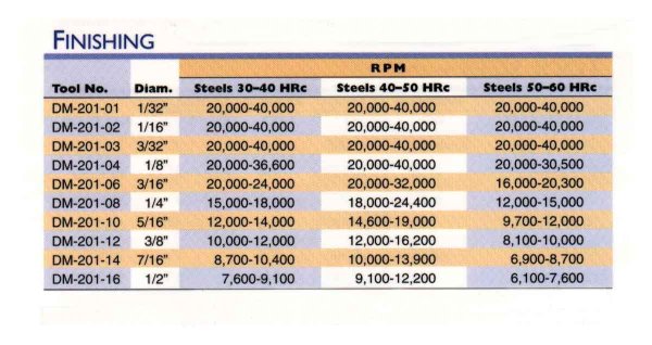
Figure 9: Recommended finishing rpm for ball end tools.
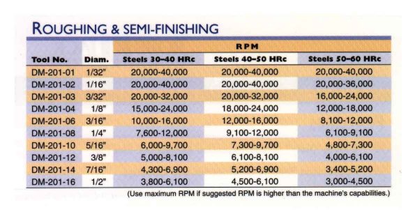
Figure 8: Recommended roughing and semi-finishing rpm for ball end tools.
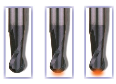
Figure 6: When a cutter is worn, the increased force and heat is evident in a red glow at the tip of the cutter.
High-speed machining (HSM) of hardened die steels should not be feared but embraced. Many people believe that hard metal machining is a black art, but with a few basic principles it is a profitable and straightforward machining process. There are several components of the process: the effective use of the machine tool, cutting tools, tool holders and programming. If these areas are addressed correctly, hard metal machining loses its mystery and becomes a predictable process where established guidelines can be used.


Choosing the Process
The three major machining methods are: soft machining, hard machining and EDM. The configuration and hardness of the die or mold material determines which method or combination of methods will work best. Soft machining-machining the part prior to heat treatment-should be considered when machining large parts or parts that require deep cuts. Then, semi-finishing and finishing can be done in the hardened state. If the part is not very large or calls for shallow machining, the entire part can be milled in the hardened state. If the part geometry requires thin features and deep cuts, EDM may be the only option.
Tool Selection
Choosing the proper cutting tool is very important when machining hardened metal. There are three basic designs of cutters: ball end, corner radius (bullnose) or square end (see Figure 1). In hard metal machining, the first choice should be the ball end mill used for roughing operations and most finishing operations. Its large radius dissipates the force and heat that is generated in cutting hard material at high speeds and feeds. The ball end mill allows the user to cut closer to the net 3-D shape and allows for higher speeds and feeds.
If a part requires large, flat areas on its floor, a corner radius tool should be used after the ball end tool has roughed out the part. The corner radius tool does not have as large a radius as the ball end tool; therefore, it does not dissipate the heat and force as well as the ball end mill. The square corner tool should be used as a last resort and only after a ball end and corner radius tool has removed as much material as possible from the part. The sharp corner of a square end tool acts as a focal point for the heat and force and will have a tendency to chip. The only time a square end mill should be used is when a sharp corner is required at the transition of a floor and a wall.
Tool rigidity also is an important factor to consider. In small diameter cutters, the shank of the tool should be much larger than the cutting diameter. This increases the stiffness of the cutter, which helps produce better finishes and longer tool life. It is important to choose the tool to fit the application. For example, series end mills that come with an eight-degree per side draft angle can be easily and quickly modified if the part has three-degree draft, the tool can be modified to 21/2x draft. Generally, a tool should have 1/2x less draft than the actual part. This 1/2x provides for angular clearance while keeping the tool as strong as possible (see Figure 2a). Additionally, the tool should not project from the holder any farther than is required. If straight walls are required, a neck can be used to strengthen the tool (see Figure 2b). Both methods allow the short-length-of-cut tool to cut deeper than its cutting length.
Controlling Heat Generation
Excessive heat changes the part's surface morphology, which reduces cutting accuracy. However, one way of minimizing heat generation and retention is by controlling the radial step-over of the cutting tool. Radial step-over is the distance between centerlines of successive, parallel cuts (see Figure 3). For roughing operations, the radial step-over should equal 25 to 40 percent of the cutter's diameter. For finishing with a given cusp height on a flat surface, the radial step-over can be calculated with the following formula:
Radial step-over determines how much heat is accumulated in the tool and the part by establishing the length of time each flute spends in the cut and how much time it takes to cool before entering the cut again. Figure 4 illustrates the effects of radial step-over and heat generation. When the step-over is too great, the flute builds up heat because there is insufficient time to cool the flute before it re-enters the part. By using smaller step-overs, there is a continuous cooling action, which controls heat generation. By regulating the heat generation with a continuous cooling action, higher rpms can be used without reaching the fatal temperature of the coating. Once the fatal temperature of the coating is reached, there is a rapid deterioration of the cutting edge, which increases force and temperature to the tool and part. When the proper process is implemented there should be no build up of heat in the part. Excessive heat leads to changes in the surface morphology and loss of cutting accuracy.
By selecting the proper coating, higher temperatures can be reached without compromising the cutting tool. For example, the maximum working temperature for titanium carbonitride (TiCN) is 750xF (400xC) compared to titanium aluminum nitride (TiAlN) with a maximum working temperature of 1,470xF(800xC).
Generally, TiAlN is the preferred coating for HSM hardened die/mold materials because of its high heat resistance. Higher heat resistance of the TiAlN coating results in faster rpms without damaging the cutting tool.
Proper speeds and feeds are essential in controlling heat buildup. Large chip loads remove heat so it does not build up in the tool or part. If the chip load is too light there is a rubbing or grinding action that leads to heat build up. Therefore, it is very important for tool life to use the largest chip load possible without damaging the tool or part (see Figure 5).
For example, if the chip load per tooth should be 0.008" and the chip load used is .002", a part that should take twenty minutes to machine will take eighty minutes; the tool spent four times as much time in the cut as required.
The geometry of the tool also plays an important role in controlling heat, affecting the way the chip is formed and evacuated from the cut. A tool should be designed specifically for hard metal machining because incorrect geometry can result in premature tool failure and poor part finishes. Flood coolant should not be used in most cases. Extensive testing showed that using flood coolant in materials above 40 HRC reduces tool life. Many methods of coolant delivery were tested-including through-the-tool coolant holes, coolant grooves, coolant hoses, high pressure and normal pressure. In all cases, there was a reduction in tool life because of the thermal shocking of the carbide tool. It is, however, very important to evacuate the chips and avoid re-cutting. Two excellent methods of evacuating chips are air or mist coolant, which should be directed as close to the tip of the tool as possible.
Tool Issues
Replacing a tool usually depends on the user's requirements. Generally, cutter failure can be seen with the naked eye. A simple way to check is to look at the tip of the tool while the tool is in the cut. When the cutter is worn, the increased force and heat is evident in a red glow at the tip of the cutter (see Figure 6). The red glow begins slowly and usually appears in corners or areas where more material is being removed. When there is a prominent, continuous red glow, the tool is usually pulled and replaced. The red glow also can indicate problem areas in the part where there is improper programming.
Consistent tooling also is important to make the process predictable. It is very important to consider the tolerances of the tools. To get a proper fit in tool holders-including shrink-fit tool holders-the tolerance on the tool shank should be -0.0001" to -0.0002" of the nominal diameter. This ensures compatibility, consistency and better surface contact with tool holders. Industry standard tolerances are up to -0.0005"; this leads to runout in the holder and improper fit. In addition, the roundness of the shank should be held to at least q0.000025".
Runout causes the chip load to increase for one or more flutes, while the other flutes cut too light of a chip-a major problem in hard metal machining. Shock from runout causes the tool or workpiece to vibrate, leading to chatter and tool chipping. Controlling runout limits the shock introduced to the cutter.
Polished shanks also should be avoided. While the tools may appear aesthetically pleasing, polished shanks reduce the holder's gripping ability. Having the proper tolerances on the tool and tool holder will insure proper rigidity, accuracy and consistency.
The Machine Tool
The machine tool should not be overlooked. Although it is possible to machine hard metal parts on older machines it is not as productive. If the machine is limited on rpm, the feedrate will proportionally suffer. It is beneficial to have a machine with the closest accuracy and the most rigidity possible. To maximize feedrates, the controller must be able to compensate for acceleration, deceleration and spindle growth. The controller also plays an important role in the ability to process the vast amount of information required for die/mold machining at high speeds. When looking for a new machine tool, it is not only important to investigate the look ahead of the controller, but also its throughput capabilities, which consist of the block processing speed, the servo response, the interpolation rate, the resolution of the feedback system and acceleration and mass.
Programming
Programming determines the way the tool engages the material as well as the type of forces induced into the tool. Therefore, programming is a critical element to the success of a HSM of hardened metal. When entering a cavity, helical interpolation should be used to minimize the variations of shock induced into the cutter. Programs should avoid straight plunging (plunging in the Z-axis only). If the programmer can't set the tool to enter the part from the side or helically, he should program it to ramp in. The programmer, who also determines the radial step-over and depth-of-cut, is critical to the HSM process. There are established parameters that can be used to insure success in HSM of hardened material (see Figure 3 and Figures 5, 7, 8 and 9).
It is important to remember that the HSM of die and mold steels is a process that consists of the effective use of the machine and cutting tools, the tool holders and programming. All of these components need to be addressed to ensure that a predictable and profitable performance will result.


Related Content

6 Ways to Optimize High-Feed Milling
High-feed milling can significantly outweigh potential reliability challenges. Consider these six strategies in order to make high-feed milling successful for your business.
Read More
Tolerancing in Mold Design, Overcoming Cutting Tool Vibration, SPE MTD Updates & More Most-Viewed May Content
Every month, MMT draws inspiration from its diverse readership's wide-ranging interests, from mold design tolerancing to cutting tools and beyond. Here are May’s top 10 most-viewed articles, based on Google Analytics.
Read More
Ten Things You Need to Know about Circle Segment Milling
Considerations for evaluating if circle segment end mills or conical barrel cutters are right for your mold machining applications.
Read More
Modular Tooling Systems Enable Versatility in Hole-Drilling Operations
The versatility of replaceable cutting edges offers users the ability to adapt to varied operations.
Read MoreRead Next

Tool Considerations for High Speed Cutting
Fast CNC processing and high-pressure coolant contribute to removing metal at dramatic rates. But what should a shop know about cutting tools in high speed machining?
Read More
How to Use Continuing Education to Remain Competitive in Moldmaking
Continued training helps moldmakers make tooling decisions and properly use the latest cutting tool to efficiently machine high-quality molds.
Read More
Are You a Moldmaker Considering 3D Printing? Consider the 3D Printing Workshop at NPE2024
Presentations will cover 3D printing for mold tooling, material innovation, product development, bridge production and full-scale, high-volume additive manufacturing.
Read More