
Cutting the Impossible
A new approach to machining deep 3D cavities and cores.
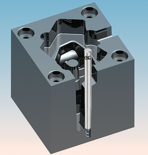
Figure 1 - 3D rendering of sample part included in the RFQ. All figures, tables and charts courtesy of OSG Tap & Die Inc.
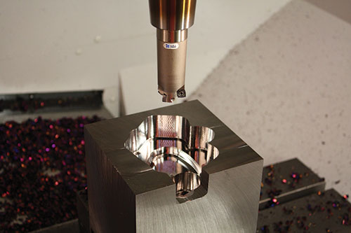
Figure 2 - Roughing with a high-feed milling cutter.
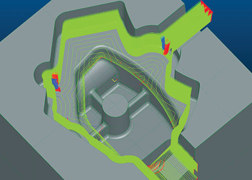
Figure 3 - Computer model of tool path.
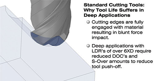
Figure 4 - As a standard cutting tool fully engages with the part, blunt force impact leads to vibration, chatter and short tool life.
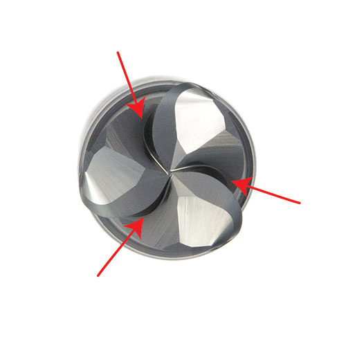
Figure 5 - Cutting tools with a spiral gash gradually engage the part and reduce blunt force impact.
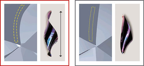
Figure 6 - The chip on the left was formed by a spiral gash cutting edge. It is thinner and longer than with a traditional tool (right). Feed rate increases with thinner chips.


We asked a handful of top mold shops across the country to quote the machining of the deep mold cavity insert shown in Figure 1, taking into account lead time and all necessary processes. A part model was provided, along with material specifications and requirements in a uniform RFQ that stated, “America Quote This.” Table 1 shows the typical responses, recommended process descriptions and delivery lead times from each shop.
In addition to these responses, the shops unanimously agreed that EDM was required for the part due to the necessary long tool lengths and small radii, as noted in the process sheet. Also, several part set-ups were required to rough the part on a mill, fabricate electrodes and finish the part in the EDM. These additional setups and processes not only add lead time to the delivery, but also create a lot of unnecessary work flow, adding to the cost of the finished part.


The challenge was clear: Find a way to dramatically reduce lead time, lower costs and achieve better profit levels. With a partnership in place between a cutting tool supplier and local machine dealer, we set out to prove that, difficult-to-machine deep mold cavity inserts and cores are possible with new cutting tool technology.
Test Time and Tool Selection
A block of H13 steel was set up in a vise on a vertical machining center, and the part was programmed. To help determine what size rougher to use, it’s important to take a few extra minutes to run cycle time simulations in a CAD/CAM system. This involves making judgments based on cusp height and the amount of material remaining in the corners.
By using a high-quality CAM system, you can view and analyze the stock model accurately. Then you can carefully evaluate the part and determine what size tools to use to get the part closest to net shape without sacrificing too much cycle time. After a proper evaluation, a 32-mm high-feed indexable milling cutter was selected for roughing this test cut.
With tool selection, bigger is not always better. By using a smaller rougher, you can access more areas in the cavity to remove additional stock, which leaves the part closer to the net shape so that subsequent tools are able to run faster, achieving better overall cycle times.
High-feed cutters are often used for cavities and other styles for the cores. The benefit of using a high-feed rougher is that it channels the cutting forces in the Z-axis direction, so you can run at very fast feed rates (Figure 2).
After initial roughing, we cleared the corners and semi-finished the part in the same program using longer tools. Usually, this machining method is problematic because of the varying stock amounts left in the cavity. The typical tooling available today causes vibration and chatter due to fully engaged cutting edges, which results in blunt force impact. This impact creates tool deflection, a harmonic effect and vibration. To help reduce these effects, the cutting speeds and feeds should be reduced. This allows the tool to take smaller cuts, minimizing vibration. Chatter and vibration also reduce cutting tool life and affect the part’s surface finish (Figure 3).
To improve the machining process, it was necessary to eliminate the long tool chatter and vibration. We employed next-generation tooling, which utilizes geometries that minimize vibration when you are hanging tools out really long to machine deep cores and cavities.
In deep applications with length-to-diameter ratios greater than six times, you must dramatically reduce the depths of cut and step-overs to reduce tool push-off. New cutting tool geometries designed for deep work allow tools to be pushed faster, reducing cycle time.
With new cutting tool designs that utilize a spiral gash geometry, the cutting tool flute gradually engages the part and channels the cutting force in different directions, reducing the blunt force impact, which minimizes vibration and chatter. Figures 4 and 5 show how vibration occurs and how it is measured.
In this test, spiral gash technology achieved the same chip-thinning effect as some high-feed cutters. This allowed the cutting tool to be fed at a higher rate than expected while displacing heat buildup on the part and cutting edge (see Figure 6).
These new tools also prevent chipping, offering improved cutting edges that are protected by cutting edge angles larger than 90 degrees. This makes the cutting edge less sharp and less fragile compared to standard tooling that uses traditional relief.
After roughing and semi-finishing with great cycle time, the part was completed with a solid carbide tool for a chatter-free finish. Tapered tools provide superior strength with minimal deflection. By using just a one-degree cutter, you can cut your tool deflection in half. A two-degree cutter on the shank of your tool can provide 60 percent less deflection than a straight-shank cutting tool (see Chart 1).
Side walls were finished to a few tenths from the bottom. This prevented the cutting tool from having dual contact with the bottom surface, which could grab the tool and leave a mark. CAM software, which uses true surfaces for its toolpath point calculation and distribution, can also help produce a superior finish.

Table 1 - These quotes received from three mold builders include processes to manufacture the part and the estimated number of hours.

Chart 1 - Solid tools with varying shank tapers offer reduced tool deflection.
Summary
By using a quality machine tool and programming system with next-generation tooling, cycle time was dramatically reduced, and the part was completed in 5 hours and 21 minutes—an 800-percent cycle-time improvement over the mold shop quotes that included traditional EDM methods. By following the approach detailed here, shop owners can compete on a higher level and secure more business.


Related Content

Solving Mold Alignment Problems with the Right Alignment Lock
Correct alignment lock selection can reduce maintenance costs and molding downtime, as well as increase part quality over the mold’s entire life.
Read More
Plastic Prototypes Using Silicone Rubber Molds
How-to, step-by-step instructions that take you from making the master pattern to making the mold and casting the plastic parts.
Read More
Fundamentals of Designing the Optimal Cooling System
The right mold components can help improve mold cooling and thereby produce higher-quality parts.
Read More
6 Ways to Optimize High-Feed Milling
High-feed milling can significantly outweigh potential reliability challenges. Consider these six strategies in order to make high-feed milling successful for your business.
Read MoreRead Next

Machining Techniques: Are You Finished Yet?
Have you ever heard that question? People who work in the mold and die industry have probably heard it more frequently than they would like to; however, great strides in cutting tool and machining techniques in the last couple of decades are enabling more “Yes” answers.
Read More
Cutting Tool Strategies for Milling Ribs
A review of machining options for tapered rib processing, typically found in plastic injection and die cast molds.
Read More
How to Use Continuing Education to Remain Competitive in Moldmaking
Continued training helps moldmakers make tooling decisions and properly use the latest cutting tool to efficiently machine high-quality molds.
Read More