
Crash Test Genius
Toolpath verification software has evolved to permit simulation of the entire machining system.


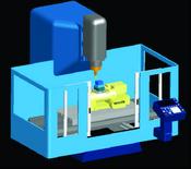
Simulations can illustrate machines anywhere from basic two-axis mills to complex five-axis tilting head machines. Images courtesy of DelcamUSA FeatureCAM.
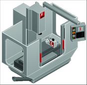
With full machine simulation, numerous machine components can be included, such as turrets, heads, spindles, tool shanks, tool changers, rotary tables, axis slides, clamps and fixtures.
OK, you’re driving the Ferrari, maybe 130 mph, down a road through the woods. You’re set for that sharp left at the end of the straight. Except it’s a right. Deep in the trees you finally stop, surrounded by broken pieces of exotic machinery. You either begin to estimate your next insurance premium, or you reset the computer and try again.
From video games to virtual tours, the combination of powerful computers and advanced software provides extremely realistic simulations of nearly every aspect of life. For example, some race drivers claim that video games help them learn difficult tracks without risk to their cars or themselves.


Global competition has forced mold-makers into their own high-speed, expensive race. The winners are the shops that can differentiate themselves from offshore producers by providing complex molds in the shortest leadtimes.
Continuing advances in machine tool and software technology are helping moldmakers compete. Fast, multi-axis machining centers and precise, powerful CAM software permit rapid machining of complex contours. Complicated cavities can be machined in one setup, minimizing time- and labor-intensive operations, such as EDM and bench finishing. Multiple axes allow optimal positioning of the cutting head and the use of shorter, more rigid cutters, resulting in greater accuracy and longer tool life.
However, as with our Ferrari, higher performance brings higher risks. In the past, when moldmakers cut straightforward cavities at moderate speeds on three-axis mills, collisions between machine components and workpiece or fixtures were relatively easy to predict and prevent. On the other hand, the tilting heads, rotating tables, and other interactive components of five-axis machines create multiple opportunities for sudden, catastrophic interference.
For about two decades, CAM software makers have provided toolpath verification software that enables shops to prove out the movement of the cutting tool across the workpiece. Now software has evolved to permit simulation of the entire machining system.
Simulating the Entire Machining System
Typically in a simulation program, the user designs CAD solids that collectively represent the CNC machine being used to cut the mold. The user also specifies how the solids move and interact, mirroring the operation of the actual machine. Tool, workpiece and spindle attachment locations are defined via user coordinate system (UCS) points consisting of an origin and three vectors (X, Y and Z) that determine a position and orientation in three-dimensional space. Once the user loads a machine design file, a postprocessor file, and CAM part file into the machine control, he or she can select the machine simulation mode and view the machining process on a virtual mill. Potential collisions and other erroneous movements can be detected and the program adjusted long before code is sent to the real CNC machining center. If a collision is detected, the simulation pauses and a dialog box appears with information on the specific components involved. Test cuts or dry runs become unnecessary.
The solids representing machine com-ponents can be modeled from scratch, or imported from CAD solid libraries. One simulation package, for example, permits definition of machine components using either the software’s own solid modeling option or solid model data imported from other CAD programs. Each solid represents a particular part of the machine, and each “movable part” of the machine is imported as an independent solid. That is necessary because presenting two machine tables or components as one solid will cause problems when one component must move independently of the other.
The user can determine exactly which machine components to add to the model, including turrets, heads, spindles, tool shanks, tool changers, rotary tables, axis slides, clamps and fixtures. Simulations of auxiliary machine functions like parts catchers and bar feeders also are possible. It is recommended; however, to keep the machine model as simple as possible. Only the necessary details should be included. Modeling every chamfer, fillet and tiny detail is only going to slow the simulation down. Once the machine simulation data are saved, they can be used with any other part program run on that machine tool.
Some machine simulations are designed to run outside the CAM program after the program is completed and saved, while others permit viewing and editing during the programming process, speeding turnaround time. Still another machine simulation module complements the software’s feature-recognition capabilities and ease of use, as well as its existing 2-D and 3-D cutting simulations, and can be used on basic two-axis mills, lathes, and mill/turn centers as well as multi-axis milling machines.
In addition to alerting users to the possibility of collisions, simulation software provides an accurate determination of cycle time. And, like the fast forward feature on a video player, simulation views aren’t restricted to running at real-time machining speeds.
All in all, machine simulation is actually very much like a CNC machine video game. Like an actual machining setup, it is based on a CNC program, features a workpiece, tools and fixturing, and requires a set of machining parameters. However, like a video game, it can be run over and over again until the user achieves the top level of performance. As such, machine simulation is an excellent way to keep rookie mold machining programmers on the road and out of the trees.


Related Content

Mold Design Review: The Complete Checklist
Gerardo (Jerry) Miranda III, former global tooling manager for Oakley sunglasses, reshares his complete mold design checklist, an essential part of the product time and cost-to-market process.
Read More
Products and Services for Multiple Moldmaking Needs
New year, new technology roundup! Featured here is a collection of product offerings, from profile milling cutters to industry-specific CAD/CAM software to innovative hot work tool steels.
Read More
MoldMaking Technology's Most-Viewed Content 2022: Products
MMT shares the five top-viewed technologies, equipment and services of 2022 in each Engineer, Build, Maintain and Manage tenet based on Google Analytics.
Read More
Mold Innovations Power Unique Auto Lighting Elements on Hummer EVs
Diamond machining, electroforming of micro-optical inserts and modified latch-lock system help injection molds produce unique forward lighting elements.
Read MoreRead Next

Verifying Machining Through Simulation
NC verification technology is one of the most useful computer-aided manufacturing tools available to moldmakers, enabling engineers to simulate the machining process of an NC toolpath in order to detect and eliminate errors before machining takes place.
Read More
Simulate and Optimize Your Mold Build Process
Mold shops can increase efficiency, lengthen tool and machine life and achieve better surface finish with the same software they use to verify their increasingly complex NC programs.
Read More
Reasons to Use Fiber Lasers for Mold Cleaning
Fiber lasers offer a simplicity, speed, control and portability, minimizing mold cleaning risks.
Read More