
Conformal Water Line Design Guidelines
Principles for creating conventional water lines are the foundation for efficient and effective conformal cooling line design.


Conformal cooling for plastic injection molds is a hot topic these days, as it can reduce cooling cycle time by as much as 30 percent, providing significant cost savings. Some moldmakers now say that as much as 40 percent of their business involves conformal-cooled mold components.
With advances in additive manufacturing, conformal-cooled mold cores are now often printed and finished in a more cost-effective manner than conventionally machined cores. These cores have a lifespan comparable to conventionally machined cores, but can be replaced in a matter of days instead of weeks.


So, what does it take to design a good conformal cooling water line that will deliver the shortest cooling time while maintaining part quality? Keeping in mind the basic principles of heat transfer is a good starting point:
Water line diameter. The diameter most commonly specified for drilled water lines is 7/16 inch. Any larger can make it hard to get the water line close to the mold surface while avoiding mold components, and any smaller could cause the drill to wander. While additive manufacturing allows us to sidestep the limitations of drilling, using a tried-and-true water line diameter is a safe bet for conformal cooling, minimizing the uncertainties associated with such an approach.
Cross-sectional area. If every water line is drilled with a 7/16-inch drill, the cross-sectional area of the drill diameter remains constant. Although conformal water lines can be made of different shapes, keeping the cross-sectional area consistent is an important principle that should be maintained regardless of the shape. This ensures a constant volume of water flowing through the water line.
Distance to mold surface. Though not a hard-and-fast rule, some shops keep the water line a distance of one diameter away from mold surfaces, while other shops may prefer a two-diameter distance. For most conformal lines, this distance would be dictated by the part geometry. At the same time, it is important that all effort be made to keep the distance a constant. This will help maintain an even heat distribution throughout the part and reduce part warpage.
Water line length. In a conventionally drilled line, water lines should be as short as possible, as drills tend to wander and break if the chips are not evacuated well. Even though it is easy to design long conformal water lines, there are good reasons to keep these lines short: The quicker the water gets in and out across the entire part, the more uniform the heat distribution.
Cross-sectional area, yet again. Since multiple short lines can hit more spots at once and carry heat away more uniformly, some conformal cooling lines are designed as capillaries, that is, a large water line that breaks into multiple smaller water lines that go short distances and quickly enter another larger line that evacuates the water. The general guideline here is that the sum of the cross-sectional areas should equal the cross-sectional areas of the inlet and outlets. This ensures an even flow of the water, further reducing the risk of warpage.
Conformal vs. Conventional
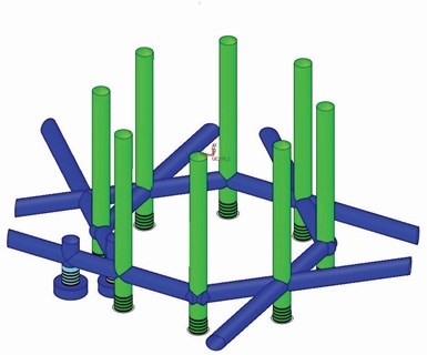
Figure 1 - Conventionally drilled water lines with baffles offer total cooling time of 50.89 seconds.
Figures 1 and 2 show two water line designs. Figure 1 is a conventionally drilled water line with baffles, and Figure 2 is a conformal water line (core side shown only). The total cooling time with the conventional waterline is 50.89 seconds, while the cooling time with conformal cooling is 44.97 seconds. This is a 12-percent reduction in cycle time.
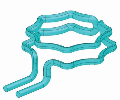
Figure 2 - Teardrop-shaped conformal water lines (core side shown only) offer total cooling time of 44.97 seconds. This is a 12-percent reduction in cycle time from conventionally drilled water lines with baffles.
Figure 3 shows a teardrop shape in which the wall is at an angle that matches the draft of the part. The inlet and outlet lines are standard 7/16-inch diameter, so a typical ¼-inch NPT connector can be used. As discussed earlier, it is important to keep the cross-sectional area consistent, therefore the teardrop shape has a cross-sectional area that matches the area of a 7/16-inch diameter line. This ensures an even volume of water is running through the circuit.
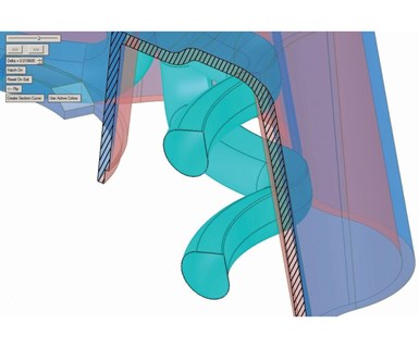
Figure 3 - For teardrop-shaped water lines, it is important to keep the cross-sectional area consistent. The teardrop shape shown here has a cross-sectional area that matches the area of a 7/16-inch diameter line, which allows an even volume of water through the circuit.
You can also avoid any sharp corners, which is a big help in printing the core. In addition, the shape of the water line makes a very small top radius, which also lends itself to better printing results.
While maintaining a consistent cross-sectional area, the teardrop shape in this example has a longer cross-section perimeter, providing more surface area for the water line to draw heat away from the mold. A 7/16-inch round line has a perimeter of 1.374 inches, whereas a teardrop line with the same area has a perimeter of 1.574 inches.
Keeping water lines short is important for maintaining even heat distribution and preventing part warpage. While the conventional line is more than 75 inches long, the conformal line, with all its curving and turning, has a linear distance of just more than 38 inches (for the sake of reference, the part itself is almost 8 inches across and 2.5 inches deep). This means the conformal water line is just about half the length, yet it results in 12-percent shorter cooling cycle time than the conventional line.
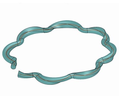
Figure 4 - This water line design has four rotations added to the top circuit that is useful for star, teardrop and plus sign shapes.
It is clear that water volume is a major factor for decreasing cooling cycle time. The greater the volume, the better. Another factor is water turbulence. While 3D printing the core will in and of itself generate some turbulence due to the unpolished inside surface of the water line, even more turbulence can be created by twisting the water line. For example, Figure 4 shows the same water line as in Figure 2, but four rotations have been added to the top circuit.
While such twisting is useless with round water lines, it can be useful for shapes such as stars, teardrops and plus signs. A more intricate shape can create a larger perimeter, so more surface area is available to draw away heat, and the addition of a twist can add even more turbulence.
You should avoid the creation of a wide flat surface across the top of the water line, however. Big, flat tops can be problematic for 3D printing (although some newer printers are better at handling these flat tops).
While these guidelines are not intended to cover everything needed for successful conformal cooling, they can serve as a good starting point. Although conformal cooling might be new to many of us, it still requires a sound understanding of moldmaking fundamentals. In fact, the very same principles that guide us in creating good conventional water lines provide the foundation to the design of an efficient and effective conformal cooling line.


Related Content

How to Select a Mold Temperature Controller
White paper shares how cooling channel analysis, which collects maximum pressure drop, total flow rate and heat dissipation, eases the performance evaluation of mold temperature controllers.
Read More
It Starts With the Part: A Plastic Part Checklist Ensures Good Mold Design
All successful mold build projects start with examining the part to be molded to ensure it is moldable and will meet the customers' production objectives.
Read More
How to Manage Wall Thickness Changes in Your Mold Design
To ensure even filling and cooling, consider wall section transitions, corners and fillets, ribs and bosses, lip and rim designs and CAE flow simulation software.
Read More
Leading Mold Manufacturers Share Best Practices for Improving Efficiency
Precise Tooling Solutions, X-Cell Tool and Mold, M&M Tool and Mold, Ameritech Die & Mold, and Cavalier Tool & Manufacturing, sit down for a fast-paced Q&A focused on strategies for improving efficiencies across their operations.
Read MoreRead Next

Integrated Software Speeds End-to-End Moldmaking Operations
Cimatron CAD/CAM software from 3D Systems helped PTI Engineered Plastics simplify the flow of its work from design to production.
Read More
How to Use Continuing Education to Remain Competitive in Moldmaking
Continued training helps moldmakers make tooling decisions and properly use the latest cutting tool to efficiently machine high-quality molds.
Read More
Reasons to Use Fiber Lasers for Mold Cleaning
Fiber lasers offer a simplicity, speed, control and portability, minimizing mold cleaning risks.
Read More