
Choosing the Right Knowledge-Based CAD/CAM System
CAD/CAM systems that offer knowledge-based machining deliver tremendous savings in both time and costs, but only when the system meets your specific needs.


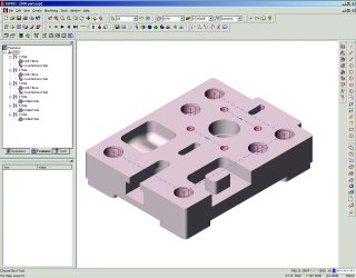
Automatic feature recognition instantly recognizes and programs all holes in an imported solid model.
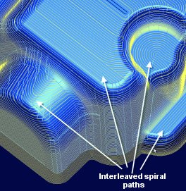
Adaptive 3-D toolpaths analyze the shape of the part to provide a superior surface finish in a single machining operation.
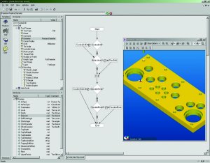
Anyone who can draw a flowchart can create an intelligent machining process.
| With the increase in the number of CAM systems that offer knowledge-based machining (KBM), more manufacturers are asking the question, "Which system is right for my shop?" This is a straightforward question with a bewildering array of possible solutions. To be honest, there is no one-size-fits-all CAM system that meets the needs of every shop. There is simply too much diversity in manufacturing processes for a single system to accommodate all the possibilities. On the other hand, there is enough competition in the CAD/CAM market to give every shop owner a one-size-fits-me solution.
Searching for the Right CAM SystemWith or without KBM, a CAM system needs to have excellent machining capabilities. Otherwise, all the automation in the world is not going to fix the underlying problem of code that doesn't work for your company. First, you must address the specific needs of your shop. A tool and moldmaker is vastly different from a high-volume production environment. Narrow the field to CAM vendors that can provide the technology to solve your problems. Then, you can make an apples-to-apples comparison of KBM capabilities that will help automate machining tasks. What all this boils down to are the following basic questions:
Who Needs KBM?As more companies embrace lean manufacturing methods-with the guiding principle of cutting waste at all levels-the importance of KBM becomes clear. A significant way to cut waste and speed production is to automate as many tasks as possible.A huge benefit of KBM is the ability to completely automate routine tasks. With KBM, 100 pockets can be programmed at the same time as one pocket. The levels of achieved automation will vary, but even if as little as 10 percent of everyday tasks are automated, that is still time and money saved for more important tasks such as bringing in more business. KBM also provides a consistent and predictable approach to machining parts. How? This improves the flow of parts through production and dramatically reduces the risk for errors when inconsistent part setups and individual CNC programmers use programming strategies. For companies wondering whether it is worth the cost to change to a CAM system with KBM, calculate the number of hours-day in and day out-for each task that could be automated. It may be costing more to stay with the status quo (see Applying Automation Table at end of article.).
Different Approaches to KBMSimply adding a database of tools, materials and speeds and feeds does not make a CAM system a KBM system. A database is just the first step, and it will be of little use unless the CAM system can automatically analyze part geometry and apply the most appropriate machining rules. This is where machinable features play a critical role. Basically, features are the key to automating CNC programming. By associating machining properties with a feature such as a hole, slot, pocket or turned profile, the critical data needed by the CAM system has a single source. Any change to the feature will update all associated toolpaths automatically. In systems that do not associate toolpaths with machinable features, a change typically requires a complete reprogramming of the part. Easy-to-use graphical interfaces are typically used in CAM software to guide users through each step of setting up data in the databases and setting up their own machining rules. Although Visual Basic (VB), a widely available programming tool from Microsoft Corp., is usually the basis for the rules controlling the automation in KBM, CAM vendors realize that most shop personnel are not VB programmers nor want to be. A CAM system may provide wizards, flowcharts or dialog boxes that let you easily set up your own customized information in the system. The CAM system should remove as many roadblocks as possible to setting up your own custom rules that define exactly how your parts will be machined. Since KBM is designed to streamline CNC programming, the method of setting up KBM data should be streamlined as well. KBM systems are based on databases of standard materials, cutting tools, feeds and speeds, and predefined machining rules that are combined with user-defined machining preferences to automatically generate NC programs. In a good CAM system, the complexities of this underlying framework are completely transparent to the user. Users easily add their own cutting tools and materials, define the types of machines in their shop, customize feeds and speeds, enter their own machining preferences and add specialized machining rules. The user then only needs to define the part material, the machine tool where it will be cut and select the part model in order to automatically generate CNC programs. The system automatically determines the appropriate cutting tools, machining operations, and speeds and feeds-all while optimizing the toolpath to cut the part as fast as possible.
Automation Versus FlexibilityThe more effort put into customizing a KBM system, the more flexible the system becomes. Most KBM systems provide a set of default machining rules. These rules are based on typical machining situations and will work quite well out of the box for many shops. A major flaw with using standardized push-button automation is that a shop will be cutting their parts the same way as anyone else using that particular software, virtually eliminating the difference between one shop and another. It is recommended that these default rules be used as a guideline, with users setting their own unique preferences for how parts should be machined. Most CNC programmers and machinists see themselves as artists, bringing their own unique talents to the job. They all want to paint the picture their own way. To create a KBM system that allows for every possible way to machine a part is an unachievable task. By automating the routine tasks, KBM is more like paint-by-numbers, allowing machinists to concentrate their skills on more valuable tasks. KBM systems typically allow for as much customization as a company wants. The only limitation is the amount of time and resources committed to customizations and an understanding of VB programming. Custom features and custom operations can be added to the standard set of features and operations the software provides, greatly expanding the usefulness of the CAM system. Any shop can create their own specialized one-click solutions that automate their CNC programming while still setting them apart from the competition.
Automatic Feature RecognitionWhen CAD models are imported into a CAM system, automatic feature recognition plays a key role in the automation process. CAM systems use automatic feature recognition (AFR) to examine an imported CAD model and automatically identify each machinable feature by type-such as hole, pocket, boss, face, etc.-and recognize their relationship to each other. CAM systems also are expanding AFR to include internal and external turned features, as well. Once these features are recognized, the CAM system can then construct a process plan to machine the entire part. AFR is performed in minutes or even seconds, depending on the CAD model. In the case of hole recognition, it can easily take less than a minute to import the CAD model, recognize every hole feature and produce all of the drilling operations in the CAM system. AFR is an emerging technology and, as such, still has a long road ahead simply because of the complexity of shapes that define a part and because of the sharing of information among CAD and CAM developers. Several CAD developers have begun working closely with CAM vendors to standardize their design information so that critical design and manufacturing data can be transferred more easily into the CAM software. Some important areas being addressed include providing a complete data set for drilling and tapping holes, transferring feature properties and annotations in addition to the geometric data, plus delivering surface finish specifications and tolerance information. Even though AFR has limitations, it does not mean that it should be dismissed lightly. AFR is a wonderful tool for recognizing standard milling features and CAM vendors are expanding feature recognition to include turned features as well. If AFR picks up the majority of features on a part, especially if those features include a large variety of holes, that is still a tremendous time savings. AFR should be seen as a useful tool that may still require some human interaction (see Does KBM Make Anyone a CNC Programmer? Sidebar).
Manufacturing IssuesA big benefit of KBM is the consistency and speed of NC code output. That same consistency must be enforced on the shop floor or the benefits are completely wasted. Machine setups must be standardized and hand manipulation of the code cannot be allowed. As standard databases and machining rules are set up in the KBM system, these same rules must apply to the shop floor itself or efforts at standardization and automation will be wasted. Manufacturing practices must be addressed before the benefits of KBM can be realized. Since KBM uses a standard database of cutting tools, those same tools must be consistently used on the shop floor. KBM systems typically allow the setup of various tool cribs to accommodate different types of machines. If a specific tool is loaded in a specific tool station in the database, that same tool must be loaded in the exact same location on the actual machine. In a perfect world, each shop would have the latest and most advanced machine tools on the shop floor. In the real world, this is simply not the case. How does KBM address the fact that most shops have a variety of machines with different controllers and vastly different capabilities? The CAM system should provide methods that allow the same part to be machined from different materials on different machines without any need to reprogram the toolpath. For example, let's say a sample mold is used to create part prototypes for the design team or the customer. The mold might be cut from a relatively inexpensive soft material on an older machine. When the part is approved, the production molds are made from a harder material on a high-speed machine. A good KBM system should let you swap out the material and the machine tool parameters, then recalculate the feeds and speeds with absolutely no need to reprogram the part. A different tool crib with specialized high-speed cutters also could be used as long as the cutting tools are the same size.
CAM TomorrowCAM software developers are not standing still in their quest for a more streamlined process and neither should moldmakers. AFR capabilities will continue to advance as the partnerships between CAD and CAM developers become stronger. As the wave of the future, KBM capabilities will become commonplace in CAM systems and provide increasingly more powerful automation solutions. KBM is an important piece in the big picture of gaining a competitive advantage, allowing moldmakers to automate redundant tasks and eliminate wasted effort.
|


Related Content

Tolerancing in Mold Design, Part 1: Understanding the Issues of Conventional Bilateral Tolerancing
Mold designers must understand the location, orientation and form limitations of conventional tolerancing before changing to another dimensioning system.
Read More
Products and Services for Multiple Moldmaking Needs
New year, new technology roundup! Featured here is a collection of product offerings, from profile milling cutters to industry-specific CAD/CAM software to innovative hot work tool steels.
Read More
What is Scientific Maintenance? Part 2
Part two of this three-part series explains specific data that toolrooms must collect, analyze and use to truly advance to a scientific maintenance culture where you can measure real data and drive decisions.
Read More
Leading Mold Manufacturers Share Best Practices for Improving Efficiency
Precise Tooling Solutions, X-Cell Tool and Mold, M&M Tool and Mold, Ameritech Die & Mold, and Cavalier Tool & Manufacturing, sit down for a fast-paced Q&A focused on strategies for improving efficiencies across their operations.
Read MoreRead Next

Software Enhances Advancing Technologies
CAD/CAM’s improved features and new capabilities—combined with the latest in technologies like high speed and five-axis machining, new cutting tools and 3-D technologies—allow moldmakers to achieve the highest quality in the shortest time.
Read More
How to Use Continuing Education to Remain Competitive in Moldmaking
Continued training helps moldmakers make tooling decisions and properly use the latest cutting tool to efficiently machine high-quality molds.
Read More
Are You a Moldmaker Considering 3D Printing? Consider the 3D Printing Workshop at NPE2024
Presentations will cover 3D printing for mold tooling, material innovation, product development, bridge production and full-scale, high-volume additive manufacturing.
Read More