
Choosing a High-Speed Spindle for Moldmaking
Many factors - such as mounting style and lubrication choices - need to be considered when choosing a high-speed spindle.


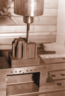
Machining a typical EDM electrode from a graphite block shows the spindle in action. The 3/8" carbide cutter is extended about three inches.
This 2.7 hp electric spindle provides speeds up to 25,000 rpm.
A powered spindle added to a machine tool can provide the higher rpm needed to perform precision milling, grinding or drilling operations with the smaller diameter tools often required in moldmaking. There are many factors to consider when selecting a high-speed electric spindle to be integrated into a new or existing machine tool. These may include features such as spindle speed range, motor power-curve and toolholding style. However, before addressing these details, it is more important to first consider the features of spindle mounting and bearing lubrication. Examining these features early in the selection process will be helpful in targeting the optimum spindle choice and it could help identify some possibilities that were not first considered.
Mounting Choices
Because the integration of the spindle into the machine tool usually imposes its own limitations on the spindle selection, this should be one of the first elements examined. Obviously, it makes no sense to consider the potential stock removal rates of a high-powered 170 mm diameter milling spindle when the available space will only permit the use of a 120 mm diameter spindle. Available space, routing of cables and tubing, spindle accessibility and ease of spindle removal are some of the factors that must be considered.


With this in mind, there are several different mounting options available.
Standard Cartridge-Style Spindle
With this option, the cylindrical cartridge-style spindle is clamped around the housing with an accurately ground split-clamp mounting block. The advantages of this style of mounting include:
- It allows the use of standard off-the-shelf cartridge spindle designs.
- It permits easy axial (Z-axis) and rotational adjustments of the spindle housing within the mounting bracket.
- Once the mounting block has been located in X and Y and squared, cartridge-style spindles can be removed and re-installed without requiring positioning adjustments (except for Z-axis).
- The spindle is usually easy to remove from the mount.
Disadvantages include:
- The split-clamp mounting block usually occupies more space than a block-style design or flange mount design.
- Increased possibility for spindle bearing failure due to uneven clamping pressures from clamping problems.
- Possible variations in axial location and orientation when a spindle is re-mounted because the spindle can be slid in and out and rotated in the mount.
- Additional weight imposed on the machine structure by the split-clamp mounting block.
Block-Style Housing
Most spindle builders can offer block-style housings. With this design, the spindle housing has one or more flat sides, allowing it to be mounted directly onto one of the sides. The advantages of this type of mounting are:
- Lower possibility for spindle bearing failure caused by mounting problems (assuming mounting surface is flat).
- It is possible to design good repeatability in X, Y, Z locations and squareness when a spindle is re-mounted (using dowel pins or stops).
- Very little extra space required. The smaller spindle footprint might allow the end user to select a larger, more powerful spindle.
Disadvantages include:
- Spindle design may be special, and the spindle typically will be more expensive than an off-the-shelf cartridge-style spindle.
- If the machine design does not include accurate location of the block housing, it may be necessary to position the spindle every time it is re-installed.
- Depending on accessibility of mounting screws, spindle removal may be difficult.
Flange-Style Mounting
Most spindle builders also can offer flanged housings, which allow the spindle to be flange (or face) mounted. This would be the preferred method of mounting a spindle in a machining center. The flange is typically a simple, round flange ring with a bolthole pattern that is permanently attached - or integral to - the spindle housing. Special designs also are possible with flats or other cut-outs as needed to accommodate the machine or tool changer design. The advantages of this type of mounting are:
- Lower possibility for spindle bearing failure due to mounting problems (assuming mounting surface is flat).
- Almost guaranteed repeatability in X, Y, Z locations and squareness when a spindle is re-mounted if an accurate pilot diameter is used.
- Very little extra space required. The smaller spindle footprint might allow the end user to select a larger, more powerful spindle.
- Mounting screws are usually exposed, so spindle removal is easy.
- The flange design can sometimes provide additional clearance to the nose of the spindle if the mounting flange can be located further back on the spindle housing. This is a big advantage in applications where the spindle must reach into cavities, such as mold work.
Disadvantages include:
- Spindle design may be special, and the spindle will typically be more expensive than an off-the-shelf cartridge-style spindle.
- Spindle can only be removed and installed one way (typically from the front).
An analysis of the machine design and investigation with the spindle builder concerning possible mounting options should help to narrow the range of possible spindle choices.
Lubrication Choices
Most builders of high-speed spindles today offer the same basic spindle model with either permanently grease-lubricated bearings or some form of oil-lubricated bearings (oil-mist, oil-air or oil-jet lubrication). High-speed spindle users understand that there will be some sacrifice made concerning maximum spindle speed if the bearings used are permanently grease lubricated rather than oil lubricated.
There are some factors that might affect the decision of which lubrication type to use. Grease-lubricated bearings clearly offer the simpler and less expensive system, with no end user maintenance requirements and no peripheral equipment needed. With any type of oil lubrication, there is maintenance involved with filling the system, making sure the airflow and oil flow adjustments are correct - maintaining a clean supply of air and maintaining the lubricator itself. Oil-lubricated bearings will require additional tubing lines to the spindle. The lengths of the lines and the routing may be critical, so these points must be accounted for. The lubrication lines must never be located where they can get pinched or kinked. In addition, most oil-lubricated spindles must establish the lubrication several minutes before the spindle is started, so this must be accounted for in the spindle start-up routine.
If oil-lubricated spindles increase the complexity of the spindle system as well as the chance for lubrication-related problems, why would an end user ever consider using this lubrication? For one thing, when properly maintained, bearings that are oil-lubricated can have a much longer service lifetime than grease-lubricated bearings. With grease-lubricated bearings, there is a finite amount of oil in the grease, and once that oil is used up, the bearings will fail. Oil lubrication never runs out. This does not mean that bearing life is infinite, but it is not uncommon for oil-lubricated bearings to achieve twice the bearing life of those lubricated with grease. In addition, oil-lubricated bearings are continuously flushing themselves of wear particles and other contaminants that can damage the bearings. With grease-lubricated bearings, once the wear particles and debris get into the grease, they stay there. Keeping the bearings clean helps to achieve maximum bearing life.
Another potential benefit of using oil-lubricated bearings relates to bearing size and load capacity. For a given operating speed, an end user might be able to select a larger spindle and use oil-lubricated bearings in order to receive the benefits of a larger bearing size (higher load capacity) and a larger shaft size (greater rigidity). For example, a 100 mm diameter spindle with 35 mm ID bearings can achieve 30,000 rpm with grease, but a 150 mm diameter spindle with 50 mm ID bearings can achieve 30,000 rpm with oil-air lubrication. If the machine design can handle a larger spindle, the additional load capacity and rigidity might outweigh the negative aspects of oil-lubrication for certain applications.
One final point to consider concerning lubrication - keep in mind the application and environment. Can oil drips or oil-mist in the air be permitted? For some environments and workpieces, it cannot. Machining of carbon-graphite electrodes for EDM machines, for example, is typically done dry and no contamination to the part is permitted. In these cases, grease-lubricated bearings might be the only option. An oil-lubricated spindle can be considered if it incorporates an effective oil-scavenge system, but this might be an expensive option if it has not been originally designed into the spindle. These are some of the many factors that can affect the final choice of a spindle. To ensure that the best spindle is selected for the application, some spindle manufacturers offer an in-house application engineering service designed to help answer these and other questions.


Related Content

Advantages and Disadvantages of Copper and Graphite Electrodes
Both copper and graphite provide approximately the same end result, so it is important for a shop to consider the advantages and disadvantages of each material in order to discover what would work best in their shop floor environment.
Read More
Forces and Calculations Are Key to Sizing Core Pull Hydraulic Cylinders
To select the correct cylinder, consider both set and pull stroke positions and then calculate forces.
Read More
6 Ways to Optimize High-Feed Milling
High-feed milling can significantly outweigh potential reliability challenges. Consider these six strategies in order to make high-feed milling successful for your business.
Read More
Treatment and Disposal of Used Metalworking Fluids
With greater emphasis on fluid longevity and fluid recycling, it is important to remember that water-based metalworking fluids are “consumable” and have a finite life.
Read MoreRead Next

Machining Center Spindles: What You Need to Know
Why and how to research spindle technology before purchasing a machining center.
Read More
Are You a Moldmaker Considering 3D Printing? Consider the 3D Printing Workshop at NPE2024
Presentations will cover 3D printing for mold tooling, material innovation, product development, bridge production and full-scale, high-volume additive manufacturing.
Read More
How to Use Strategic Planning Tools, Data to Manage the Human Side of Business
Q&A with Marion Wells, MMT EAB member and founder of Human Asset Management.
Read More