
Causes of High-Speed Machining Irregularities
A series of high-speed machining trials to machine the core of a mobile phone to near finished quality reveals the causes of flaws in the surface quality.


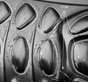
Figure 4: Gouging in button areas.

Figure 1: Set of five mobile phone cores.
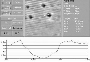
Figure 9: 3-D surface from laser probe.
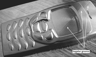
Figure 23: Overall appearance of Part 5.
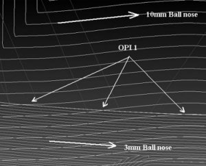
Figure 19: Oblique path intersections at OPI 1.
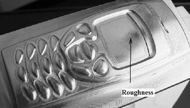
Figure 21: Overall appearance of Part 4.
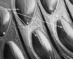
Figure 15: Ridge marks along button tops.
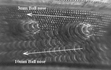
Figure 17: Detail of marks at OPI 3.
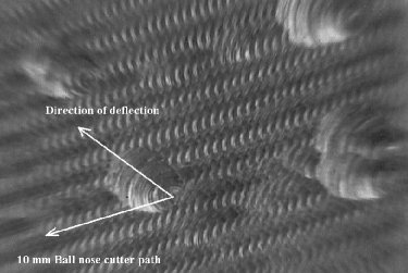
Figure 8: Enlarged detail of dwell marks.
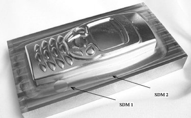
Figure 2: Overall appearance of Part 1.
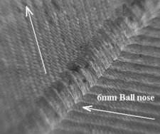
Figure 12: Detail of the grooves.
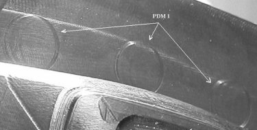
Figure 6: Periodic dwell marks -- 12mm endmill.
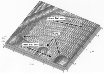
Figure 20: Laser surface showing OPI 1 in Part 2.
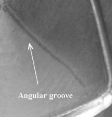
Figure 25: Groove in the display area.
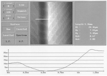
Figure 14: Cross section of groove (Part 2).
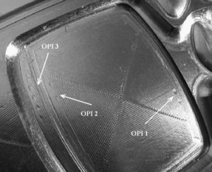
Figure 16: Clusters of sperm-like marks.
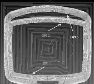
Figure 18: Oblique path intersections.
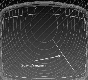
Figure 26: Cutter paths in the display area.
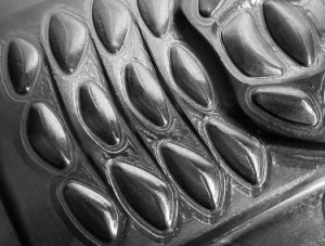
Figure 10: Poor surface finish between the buttons.
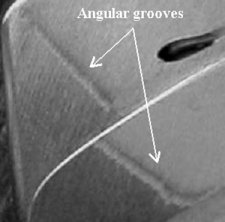
Figure 27: Grooves on upper region.
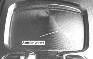
Figure 24: Angular groove on display area.
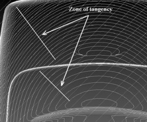
Figure 28: Cutter paths on upper regions.
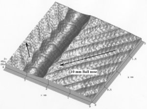
Figure 13: Laser surface image.
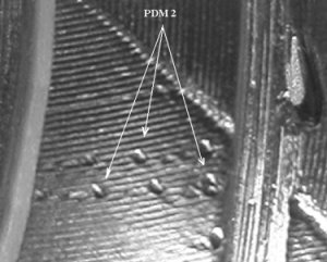
Figure 7: Single dwell marks -- 10mm ball nose.
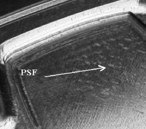
Figure 3: Surface pitting in descending areas.
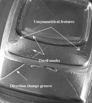
Figure 5: Major blemishes in Part 2.
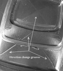
Figure 11: Direction change grooves.
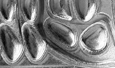
Figure 22: Channel marking around buttons.
In 2001, the core for a mobile phone was machined on a Matsuura high-speed machining center in Delcam International plc to demonstrate the benefits of applying high-speed machining strategies to generate efficient toolpaths. Unfortunately, the quality of the part was unacceptable and an investigation was started to account for the poor results. The reasons for the poor appearance were not obvious and individuals had their own opinions as to the possible causes. This uncertainty led to the re-machining of the part to produce an acceptable product. To date, the five parts shown in Figure 1 have been machined in a series of applications to assess the influence of particular factors on the machining process. These factors include the condition of the machine tool, the capability of the CNC system, the quality of the cutting tool system, the cutting strategies within the CAM system and the interaction of the CAM operator and the machine tool operator with the planned sequence of events. This article considers the results of the machining trials and reports on the possible causes of the high-speed machining irregularities.
General Approach
The applications were directed at the machining of the phone core in AISI P20 cold work tool steel with high-speed machining techniques. The goal was to machine the part to a standard that required no additional finishing processes, i.e., no benching. This part has many intersecting surfaces and areas where it would be anticipated that machining would be problematic. For example, the general convex nature of the part presents many sections where machining on down slopes is unavoidable, a known difficulty in high-speed applications. In each application, the production of the CAM files was done in PowerMILL and the cutters were all from the Shinko Kobelco (Al,Ti)N "Miracle" range.


Methodology
Each part was examined visually after machining and assessed for overall appearance and particular flaws. These assessments were initially subjective with personal opinions being expressed by interested parties. Analytical quality assessment techniques have been used to measure particular features. The general appearance is important because this gives the first impression of the accuracy of a machined part even though it has no defined quality value associated with it. In some cases, the overall appearance would determine the acceptability of the part. Flaws, such as individual marks, also are important because they stand out in the part and may compromise an otherwise acceptable job. The procedure, therefore, has been to look at each part and determine the reasons why the quality was compromised. The results for each phone core will be presented as a series of flaws accompanied by the most probable explanations of their causes. In some cases, the explanations are speculative at this stage and require more work to substantiate them.
Machine and Toolholding Systems
Parts 1 and 2 were machined on a Matsuura MC-80 VF high-speed machining center purchased in 1993. This machine had given eight years of good service but could not be considered now as up-to-date, high-speed technology. In particular, the Yasnac iT80 control system is a first generation high-speed system with limited data processing capabilities. The BT40 cutting tool system (contact taper 30/60 percent) was purchased with the machine and, as such, no longer conforms to the current higher-speed standards.
Parts 3 and 4 were machined on a Bridgeport VMC1500 purchased in 1998. This machine had a more up-to-date specification and five years less production service than the Matsuura. The Heidenhain T430 is a well-respected control system providing a range of high-speed control features. The BT40 cutting tool system (used to machine Part 3) also was purchased with the machine, but it was upgraded to exceed the latest Japanese taper contact standard (80 percent) prior to the machining of Part 4.
Part 5 was machined on a new Mikron HSM700 with a Heidenhain ATEK HS-Plus control system. This high specification machine and tooling system was in excellent condition (less than a year old). The ATEK is an advanced high-speed controller.
CAM Preparation
A machinist with eight years of experience operating the Matsuura high-speed machining center prepared the NC files for Part 1. Identical CAM strategies for Parts 2 and 3 were conceived by an application engineer who was aware of the basic principles of high-speed machining, but had limited experience of the new cutting tool developments. An application engineer, who had experience in the new techniques of high-speed machining, generated the NC files for Part 4. The CAM approach to Part 5 was different to the previous four in that the strategy was generated by recently developed automatic high-speed routines. In all cases, the cutter paths and cutting conditions were prepared with the best intentions but the results, which improved gradually, were not always as good as expected. However, the incremental improvements did offer the opportunity to account for the poor appearances at each stage and move towards an acceptable phone core.
Machining Strategy: Part 1
The machine tool operator of the Matsuura MC-80 VF high-speed machining center prepared the NC programs for Part 1. This operator was an experienced machinist who had a general awareness of the new CAM strategies for high-speed machining, but who had not been re-trained on the recent developments in tooling and strategies. The general approach to the removal of the material does not follow the current high-speed guidelines that promote continuous light, very fast cuts in climb-milling mode. The sequence of operations was a mixture of short conventional and climb-milling paths that are compromised by full diameter cuts in certain areas. The bulk of the metal was removed with a 12 mm endmill following raster area clearance and pencil corner strategies. The main surface form was machined with a mixture of raster and 3-D offset strategies with ball nose cutters ranging from 6 mm down to 0.6 mm. This confused view of high-speed milling also was demonstrated by the inappropriate use of flood coolant in the early stages of production. The Matsuura took more than five hours to machine the part.
Overall Surface Appearance
The overall appearance of the main form is dull and mottled (see Figure 2). On several occasions, the cutter plunged too deep into the material and the finish between the buttons is very rough. Gouging has occurred on some of the links on the cutter paths. The two-way, raster strategy used to finish the part has not produced a bright effect on the major surfaces of the part. This is not surprising because the two-way approach will drive the cutter in climb and conventional mode alternatively. The climb mode should provide good high-speed cutting conditions, whereas the conventional mode goes against current high-speed conventions.
Single Dwell Marks (SDM)
The single dwell marks SDM1 and SDM2, seen in Figure 2, occur at the start and end of cutter paths, when the cutter (12 mm endmill) was in contact with the surface of the billet. These round marks coincided with Z-axis moves directly onto the part at the lead-in and lead-out stages of the cutter paths, and should be avoided by a better choice of lead-in and lead-out strategies.
Pitted Surface Finish (PSF)
The display surface (see Figure 3) is pitted with blemishes in the descending surface areas where the cutter may be losing contact with the surface. It is generally accepted that the cutting conditions in such areas are poor because the contact zone between the cutter and the material changes from the programmed climb-milling mode to a mixture of climb and conventional interactions. Similar effects were encountered in the same area of Part 4, where the raster strategy was correctly restricted to the climb-milling mode.
Cutter Gouge Marks (CGM)
The buttons were finish machined with a 0.6 mm ball nose cutter following the two-way raster strategy. The gouges across the surface of some buttons (see Figure 4) match the link lines in the cutting file and result from the cutter being too deep relative to the button surfaces. The 0.6 mm ball nose cutter paths also scar the area surrounding the buttons where isolated paths come close to the base of the buttons.
The probable causes of these gouge marks relate to the setting and maintenance of tool lengths throughout the machining process. Previous surfaces could have been cut too high (compensation for tool length shorter than required), or the current tool is longer than required and cutting too deep. A 0.6 mm cutter needs to be held in a reliable, accurate location to prevent run-out and deflection. The cutting tool holders were purchased with the machine in 1993 and these are now well below current high-speed standards. It is essential that the machine operators maintain the highest possible tool length control during the machining operations.
Machining Strategy: Parts 2 and 3
The extent of the progress in machine development is apparent in the comparison of Parts 2 and 3 that were machined on the Matsuura and the Bridgeport, respectively. The same CAM cutting paths, machining parameters and cutting tools were employed on both jobs and these similarities, therefore, offer the opportunity to assess the influence of the machine tool. The CAM operator was an experienced application engineer, who had an awareness of the new CAM strategies for high-speed machining, but had not yet been trained in their specific use. The bulk of the metal was removed with a 12 mm endmill with a 1 mm tipped radius following pattern finishing and 3-D offset strategies. The main form was machined with a 10 mm ball nose with the finishing detail produced from a succession of 3, 2, 1 and 0.6 mm ball nose cutters. The Matsuura took more than seven hours to machine Part 2, whereas the Bridgeport took more than four hours to finish Part 3. The three-hour difference is attributable to the comparative processing times of the respective control systems.
Overall Surface Appearance
There are marked differences in the appearances of the two parts. In particular, Part 2 is characterized by the many blemishes shown in Figure 5. Some of these marks (direction changes) are reproduced in Part 3, supporting the view that they are inherent in the CAM strategy. Other types of blemishes (dwell marks) do not occur, or occur to a lesser extent in Part 3, suggesting that they are machine dependent. There also is an inconsistency in the geometry of the two parts (unsymmetrical features in Part 2) that was unexpected.
Unsymmetrical Features
The unsymmetrical features (below the display area) in Part 2 are not repeated in Part 3 and would not be expected from the symmetry of the cutting files. Something happened during the machining cycle to alter the positional relationship between Part 2 and the cutting tools. Part 2, if clamped insecurely, could have been moved in the fixture by the machining forces, but this is unlikely considering the light machining conditions in high-speed machining mode. The more probable reason for the machining error is that the part was removed from the machine setup, possibly for inspection, and reset inaccurately before completing the machining operations. The cut surfaces suggest that the part was tilted upwards slightly from the top right-hand corner of the part, as shown in Figure 5.
This would result in subsequent cutters machining deeper than required in the region where the symmetry is lost. Unfortunately, nobody admits to this happening. The main point to be gained from investigating this flaw is that, in high-speed applications, the part should not be moved from the setup during machining, because the tolerances are too tight to guarantee re-establishing the relationship between the part and the cutting tools. Also, it is essential that the setting and maintenance of the cutters are controlled to the highest standard, otherwise cutter length and diameter errors will be introduced to the machining environment, which will compromise the accuracy of the part.
Periodic Dwell Marks (PDM)
- Endmill on a flat surface - The series of round (PDM 1) cutter marks around the boundary of the core profile occurred only on Part 2 (see Figure 6). It was unexpected to see the marks in this particular situation as the profile is changing very slowly in constant Z and the machine should be cutting in constant high-speed motion. First impressions, which proved to be correct, were that the cutter was dwelling intermittently due to data processing limitations.
- Ball nose on a curved surface - The set of intermittent (PDM 2) marks also occurred only on Part 2 (see Figure 7). These marks lie on the cutter paths of a 10 mm ball nose cutter as it climb mills the final profile of the core in a 3-D offset strategy. As in the previous case, suspicions for these marks were directed towards data processing problems in the Yasnac controller. However, this reasoning had to be tested because more instances would be expected over the whole shape, where similar point densities occur in the cutting paths, and no marks were found.
- The enlarged image shown in Figure 8 highlights the cutter centerline as the lighter detail with the cutter mark angled across several 0.3 mm step-over paths. In climb-milling mode, the cutter appears to dig in along this angle of contact when the machine motion is interrupted, and the load, therefore, altered. The degree of indentation (10 microns) is shown in the laser surface image in Figure 9, and would be dependent on the stiffness of the machine/cutter holder/cutting tool combination.
Why Don't These Marks Occur More Frequently?
The answer to this question, unfortunately, is vague. There is no evidence that marking has occurred in other areas, but many of the surfaces have been revisited by cutters in the finishing processes, and marks could have been machined out. Secondly, all of these cuts were in climb-milling mode, with the curvature of the part changing constantly (up-slopes and down-slopes). This would change the relationship between the cutter and the part and could influence the degree of marking caused by a motion stop. Finally, the operator confirmed that manual intervention, i.e., feedrate override, was used to maintain stable cutting conditions. This would take the form of the operator anticipating where the problems were liable to recur and slow the machining rate. The extent of this latter factor cannot be determined from the machined part.
Poor Surface Finish Between the Buttons
The Matsuura and the Bridgeport spent much of the cycle time cutting the highly scarred areas around the buttons (see Figure 10).
The NC cutting files are heavily congested in the areas between the buttons with very short linear spans between the data points. The reason for this concentration of data points lies with the way in which the CAM system was operated and not on the CAM routines themselves. This will be discussed later when the issue of data processing times is covered.
Both machines were seen to dwell in these areas for significant periods of time and this accounts for the long cycle times for Parts 2 and 3. Conversations with the machine operator confirmed that the machines did exhibit intermittent cutting in all of these areas, and that this phenomenon was a common occurrence on other parts. The general shop floor opinion was that, in certain circumstances, the control systems could not keep up with the data processing requirements for the cutter paths. In these cases, the machine operator's views were correct with two factors, namely the DNC transmission time and the NC block processing time contributing to the intermittent motion.
DNC Transmission Time
The Yasnac i80 M control system on the Matsuura, bought in 1993, is a first generation high-speed control system that cannot store very long programs in the resident memory. It has, therefore, to accept drip-fed blocks of data from a computer via a DNC link. The speed of this data transmission is dependent on the specification of the link, in this case an RS232 C link operating at 38.4 Kbaud. This limits the amount of data being transmitted to one character per 0.026 ms, i.e., approximately 0.34 ms for a typical NC block in the cutting path (13 chars/block) that produced the PDM 1 marks.
The DNC facility does not allow continuous drip feed and has, therefore, to batch the data into larger packages. The size and frequency of the flow (not constant values) depends on the data processing capability within the Yasnac. The controller does have a buffer storage facility to retain 20 blocks of NC code in advance of the current move. The worst case, i.e., to fill an empty buffer, would require 6.8 ms, which is equivalent to moving 0.57 mm at 5 m/min. However, even with a full buffer, the processing of the data is not instantaneous and time is required to convert the data into machine command information to keep the machine moving quickly.
NC Block Processing Time
The interval of the PDM 1 marks around the profile of the block is approximately 25 mm. There is a constant number of 84 data points between each mark in the NC cutting file with a linear span between the data points of 0.3 mm. The internal data processing time specification of the Yasnac is 10 ms/NC block, which is the quickest time possible to send commands to the machine. This time requirement will increase when data is being sent via the DNC link. Therefore, at best, the machine will struggle to maintain constant motion if the consistent interval between the point data in the NC cutting path divided by the feedrate is greater than 10 ms. The actual programmed rate of 5 m/min could not be achieved, because at 10 ms/NC block and 0.3 mm linear span the maximum speed of the machine reduces to 1.8 m/min.
The Heidenhain TNC426 on the Bridgeport is a faster control system with a NC block processing time of 4 ms. The 0.3 mm interval between the data points also occurred in Part 3, but the Bridgeport can machine this span data at a maximum feed rate of 4.5 m/min, i.e., close to the programmed 5 m/min. This faster capability reduced the overall machining between Parts 2 and 3 by three hours and the periodic circular marks were not produced in Part 3.
The cutter paths in the region of the PDM 2 marks move the cutter from right to left immediately after cornering on a 3-D offset strategy to move up the part. The point data is very dense in this area, with 0.155 mm between each point. The Matsuura is incapable of processing this data faster than 0.9 m/min, which is well below the programmed value. Part 3, which was machined on the Bridgeport, did not encounter this problem. The Heidenhain TNC426 can process the 0.155 mm linear interval at 2.3 m/min, which was near to the programmed feedrate value. The data flow requirement could, therefore, be within the specification of the control system.
A typical linear span in the regions where the poor surface finish was produced in Parts 2 and 3 is 0.005 mm and, although not as pronounced as the effect on the Yasnac, the Heidenhain TNC426 also appeared to be struggling to process the data in real time. The 10 ms NC block-processing rate on the Yasnac restricts the maximum feedrate to 30 mm/min and the 4 ms NC block processing time on the Heidenhain increases this rate to only 75 mm/min. These speeds are far short of the feedrates associated with efficient high-speed machining. In such cases, the machine will not adjust automatically to a constant lower feedrate, but attempt to move at the higher rate until the periodic data starvation occurs, i.e., stop/start motion.
Matsuura acknowledges that this can happen in the Yasnac i80M. The current generation of Yasnac control system, the J300B, allows much higher processing speeds and supports larger NC programs. This latest system permits continuous 1 mm linear moves at 60 m/min, i.e., 1 ms/NC block (ten times faster than the Yasnac i80M). PCMCIA cards support larger memory provision (160 MB) and allow very fast uploading and downloading of programs via an Ethernet communication (TCP/IP). The latest Heidenhain iTNC530 control system has a block processing time of only 0.5 ms.
Machine Operator Influence
Significantly, the machine operator reported that the Matsuura was stopping intermittently in the region of the single dwell marks and that manual intervention was necessary to maintain safe cutting conditions. This took the form of reducing the feedrate via the manual override facility. The influence of the machine operator cannot be overstated in such circumstances. All the pre-planned cutting conditions were overruled and there is no record of the actual machining parameters. It is essential in high-speed machining that this influence is removed (or minimized) because the operator cannot change the cutting parameters quickly or accurately enough to ensure efficient cutting conditions.
CAM Operator Influence
The CAM operator, who prepared the CAM files for Parts 2 and 3, knew about the basic principles of fast, light cuts in climb-milling mode but had difficulty in applying these principles to the complex geometry in Parts 2 and 3. The CAM system in question has robust high-speed machining strategies that produce excellent results, but the operator intervened and applied editing commands to produce the cutter paths with an excessive concentration of data points. These cutter files were, therefore, not checked automatically for gouging and excess data points - the main causes of most of the dwell-related flaws in Parts 2 and 3.
Direction Change Grooves
The overall appearance of Parts 2 and 3 also are characterized by angular grooves (see Figure 11), with the detail shown in Figure 12. These grooves occur at the major direction change positions in a 3-D offset finishing strategy where corner smoothing with arcs has still to be resolved. The grooves run from the corners of the boundary profiles in towards the center of the machined surface. Similar diagonal grooving can be seen in the phone display area where a spiral 3-D offset strategy was machined from the center outwards.
The change positions are defined by linear increments that require individual NC blocks of code to direct the motion. In this case, the phone cores were aligned with the X- and Y-axis and the cutter paths ran parallel to them. This arrangement means that the machine motion is predominantly in single axis mode, i.e., either the X or Y is moving at near full feedrate with the other moving slowly. As the direction change position approaches, the faster moving axis decelerates to zero speed at the corner with the other axis accelerating to full feedrate on leaving the corner. This combination of axes motions results in a momentary dwell at the corner where the load on the cutter is reduced. The pause in cutter motion at the corner could results in the cutter digging in for several rotations to leave the characteristic mark. The precise nature of this reduction remains to be determined, but factors such as cutter deflection, toolholding stability and axes play (the Z axis in particular) could affect the desired geometric relationship between the cutting edge and the part. The consequent effect, which is exaggerated in high-speed mode, is apparent in the form of the grooves. This can be seen in the laser surface images in Figures 13 and 14.
Machine Tool Influence
The direction change grooves occurred on Part 2 (machined on the Matsuura) and Part 3 (machined on the Bridgeport). The position and character of the grooves were similar, but the depth of grooving was consistently different. The older Matsuura produced deeper grooves - 10 microns (see Figure 14) - compared with six microns for the Bridgeport.
All other factors, including machining strategy, tool holding, cutting tools and machining parameters, were the same. This suggests that the undesired relative movement of the cutter in the Z-axis is attributable to play in the spindle assembly or sloppiness in the guide-ways. It is anticipated that a better machine tool with higher-class tooling would still show the characteristic marks, but the degree would be limited to the visual appearance and not the obvious indentations seen in Parts 2 and 3.
Ridge Marks
The marks across the ridge of the button tops in Parts 2 and 3 (see Figure 15) also coincide with the change in direction of the cutter in 3-D offset mode. The cutter stops moving at this position to change the direction of the cut and it may experience relief from the deflection due to cutting load removal. The ridge also is a hostile area for the cutter because the nature of the cutting action changes as the cutter ascends to the ridge and then descends on the other side. A raster strategy produced a superior finish in Part 4.
Oblique Path Intersections (OPI)
The clusters of sperm-like marks around the phone display area (see Figures 16 and 17) are very prominent in Part 2, and also occur to a lesser extent in Part 3. First impressions, based on visual examination, led to the wrong conclusion that these marks occurred at the ends of cutter paths prior to the cutter retracting from the surface. Further investigations revealed a much more interesting situation where the angle of intersecting cutter paths influenced the cutting action.
A 10 mm ball nose with a 0.3 mm step-over generates the surface of the display area following a 3-D offset spiral strategy. The characteristic grooving at the cutter direction changeover positions are visible in Figure 16. The cutter paths featured in Figures 18 and 19 spiral out from the center of the display area in a counter-clockwise direction. The outer edge of the display area is finished with a 3 mm ball nose with a 0.075 mm step-over, again cutting in a counter-clockwise direction. Both cutter paths were generated in climb-milling mode.
Location of Sperm-Like Marks
The cutter path for the 10 mm ball nose progresses from left to right and is clearly seen as the larger set of cuts in Figure 20. The finer 3 mm ball nose cutter paths cut across the larger cusps at a slight angle from left to right. It is at the first encounter of this intersection that the marks appear. This oblique relationship between the cutter paths occurs in several places on the phone core and in all instances the sperm-like marks appear. As in the case of the direction change grooves, the character of these marks are the same for Parts 2 and 3, but the laser surface analysis indicates that the depth of those in Part 2 are again deeper than in Part 3.
A possible explanation for these marks occurring is that the 3 mm cutter is machining through a deep cusp formed by the 10 mm cutter and the cutting conditions are changing dramatically as it proceeds. The initial encounter is a high wall of the cusp being breached in climb-milling mode. As the cutter progresses beyond the top of the cusp, it breaks through into the other side of the cusp and changes the character of machining to conventional milling mode. This transition period is an unfavorable one for machining because the forces on the cutter will not be constant in magnitude or direction. It could be that the unstable nature of the machining deflects the cutter and produces the mark. More investigation is needed to establish the actual cause of this recurring feature.
It is difficult to imagine what is happening in this situation, but the following analogy may help. Imagine that a farmer ploughs a field in parallel furrows (the 10 mm ball nose cutter paths) and that you have to ride a bicycle with narrow wheels (the 3 mm ball nose cutter) across the field. The easiest way would be to follow along the parallel path of the furrow. If required, the field could be traversed normal to the furrows with regular periodic ups and downs. The most difficult method would be to attempt to cross the field at a slight angle to the furrows because the wheels of the bicycle would tend to be deflected back into the main furrow. The greater the angle of attack into the furrow, the more regular would be the direction and magnitude of the forces reacting against the motion.
Machining Strategy: Part 4
An application engineer, who had been trained in the latest high-speed machining techniques, programmed new cutting strategies and machining conditions for Part 4. The BT40 cutting tool system on the Bridgeport was upgraded to high-speed standard prior to the machining of the part. The new shrink-fit (slim-line) chucking system from MST has a minimum spindle taper contact of 85 percent (the Japanese standard is 80 percent) compared to the 30/60 percent taper contact in the European standard. The bulk of the material was removed with a 25 mm endmill in an efficient profile climb-milling mode followed by a 12 mm endmill to form the base shape. The part was completed in a series of alternate raster and 3-D offset strategies with 6, 3 and 0.6 mm ball nose cutters. The cutters were in continuous high-speed motion, and the time taken to machine the job was 2.5 hours.
Overall Surface Appearance
With two exceptions, the overall appearance of Part 4 (see Figure 21) is much better than the other three parts. The rough appearance, particularly in the descending surfaces, suggests that the 6 mm ball nose cutter was "picking up" material as it raster cut across these surfaces, similar to the marking in Part 2. There was some doubt expressed by the machinist about the deteriorating quality of the 6 mm ball nose cutter as it progressed.
Machine Operator Intervention
The machinist switched the order of the final cuts to finish with corner-picking cuts around the buttons instead of rastering overall with a larger cutter, a strategy that gave better results in Part 5. This could account for the channel-type marking in Figure 22.
Machining Strategy: Part 5
Part 5 was the last phone core to be machined in this series. It differs from the previous four in that the CAM strategies were produced automatically from the CAD data. The finish climb-milling cuts were produced on a one-way raster strategy at 45- to the machine axes. The part was machined on a new Mikron HSM700 with a Heidenhain ATEK HS-Plus control system. This machine was in excellent condition (less than a year old) and the ATEK is an advanced HS controller. The tooling also was to the latest high-speed specification. It was thought that this combination of machine and tooling could minimize the sources of error connected with the setup and thereby machine a better part. The machining time of more than seven hours is lengthy, due to the very small depth increments produced by the automatic CAM routines.
Overall Surface Appearance
This phone has the best overall appearance of the five applications (see Figure 23). The surfaces are smooth and the blending from one surface to another is very good. However, the overall appearance is impaired by the angular grooves that run diagonally across the display area and the upper surfaces of the phone core. Although highly visible, these grooves are not detectable by feel (i.e., the surface remains smooth and continuous). However, they impact on the overall surface appearance and would be unacceptable if left as seen. A manual finishing operation would remove them quickly, but this would be counter to the desire to produce finished parts directly from the high-speed strategies.
Tangential Path Intersections
The areas, shown in Figure 24, have a grain-like appearance and were cut with a constant Z strategy (radiating cutter paths) followed by 45' raster paths (bottom left to top right).
Location of the Grooves
As can be seen in Figure 25, the groove coincides with the tangency conditions between the constant Z cuts and the first raster cuts. The locus of the tangent points has been superimposed on the cutter paths in Figure 26 to demonstrate the coincidence.
Similar cutter path conditions exist in the upper areas of the core where the other instances of grooving occur (see Figure 27). The superimposed loci of points of tangency in Figure 28 again match the location of the grooves.
Proposed Causes
At this time, it is not known what caused these angular blemishes, and work is proceeding to investigate them thoroughly. Initial thoughts center on the variation in cutting load through the zone of tangency and changes in cutting action through the variation in the surface gradients. In the former case, the constant Z strategy will have produced cutter paths with cusps that follow the contour pattern. The following raster cutter paths machine across the constant Z paths before reaching the zone of tangency.
Prior to this stage, the cutter is under load and ascending the slope of the surface. At the tangency position, the cutter enters the channel between the cusps, and is not under load for a short period of time. It is possible that this load removal relieves any cutter deflection to plunge the cutter slightly deeper. Beyond the tangency point, the cutter reverts to the previous loading and deflection conditions.
The other possible cause relates to the changes in surface curvature in the zone of the grooves. As the cutter approaches the tangency position, it is ascending the surface and cutting in a preferred climb-milling mode. At the point of tangency, the cutting conditions change as the cutter starts to descend the slope. This falling condition is not conducive to good milling and could leave a mark in the transition zone.
Conclusions
The results of high-speed machining trials to machine the core of a mobile phone to near finished quality have been reported in this article. Five similar parts were machined in a series of applications to assess the influence of particular factors on the machining process. An attempt has been made to account for the blemishes on the five parts, but much more work needs to be done to find the definite causes of all the flaws. The factors included the condition of the machine tool, the capability of the CNC system, the quality of the cutting tool system, the cutting strategies within the CAM system, and the interaction of the CAM operator and the machine tool operator with the planned sequence of events. Parts 1, 2 and 3 were unacceptable in terms of visual quality and machining time. Part 4 came close to satisfying the visual criteria in the quickest machining time of 2.5 hours. The surface quality of Part 5 was the best achieved, but the machining time of more than seven hours would not be economical.
The lessons learned from this series of trials were applied to the machining of a sixth phone core in harder steel (62 HRC). This part was produced to a very good visual quality on a Hermle C600U in less than 1.5 hours.


Read Next

How to Use Continuing Education to Remain Competitive in Moldmaking
Continued training helps moldmakers make tooling decisions and properly use the latest cutting tool to efficiently machine high-quality molds.
Read More
Are You a Moldmaker Considering 3D Printing? Consider the 3D Printing Workshop at NPE2024
Presentations will cover 3D printing for mold tooling, material innovation, product development, bridge production and full-scale, high-volume additive manufacturing.
Read More
Reasons to Use Fiber Lasers for Mold Cleaning
Fiber lasers offer a simplicity, speed, control and portability, minimizing mold cleaning risks.
Read More