
CAD/CAM/CAE Integration Eases Flow Simulation
Moldmakers benefit from having flow simulation as part of the CAD/CAM environment—reducing the time and effort involved in running a flow analysis study and getting the product to market.
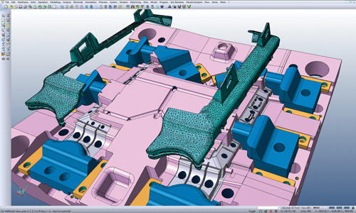
Figure 1: Integration of CAD/CAM and flow software increases productivity and simplifies the steps involved in going from concept to production. Figures courtesy of Vero International, Inc.

Figure 2: Separation between CAD and flow software is counter-productive.
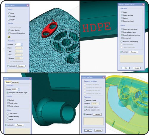
Figure 3: a. Edit geometry; b. Repair surfaces and create solids; c. Modify blends and d. Remove lettering. Parts can be repaired and modified before creating the mesh.
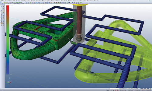
Figure 4: Edit runner and cooling systems inside the tool.

Figure 5: Integration allows importing of files in almost any CAD format, which can be edited and repaired using CAD tools.
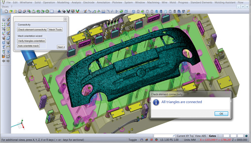
Figure 6: Mesh preparation is faster and easier with the help of the integrated tools.
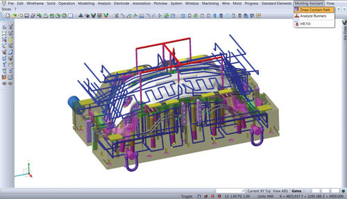
Figure 7: New functions encourage designers to include runner and cooling system in the simulations.
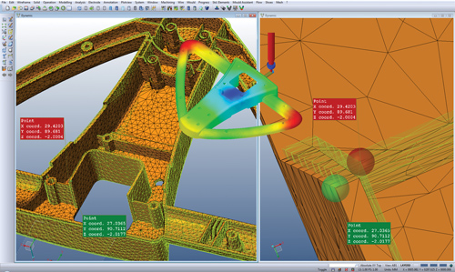
Figure 8: a. Warpage contour result; b. Overlay of original and warped model.
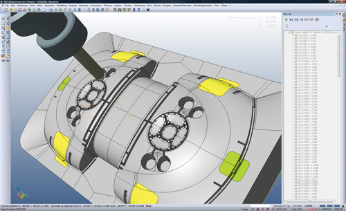
Figure 9: Toolpaths can be generated on the mold components optimized by flow simulation using integrated CAM functionality.


A new approach involving integrating flow simulation software with CAD/CAM software will be discussed in this article. We will show how CAD/CAM/CAE integration reduces the time and effort in running a flow simulation (See Figure 1). Flow simulation software products have had limited modeling capabilities and no machining capabilities. In a typical design optimization study, the designer would have to go back and forth several times between the CAD software and flow simulation software to optimize the part and mold design. Once the study was completed, the optimized design would have to be transferred to the CAM software for machining. This approach added hours (if not days) to a mold design project, especially if the designer did not have the CAD software from which the file originated. Unfortunately, this approach has been the only option available to the tooling industry (see Figure 2).


Improved CAD Tools
Integrating CAD/CAM/CAE allows the designer to build the part and tool from scratch and to make changes to imported files inside the flow simulation software. Important part attributes such as wall thickness, ribs, bosses, diameters, holes and radii can be modified. Damaged surface models can be repaired and closed to a solid using the CAD surfacing and solids modeling tools (see Figure 3).
The CAD tools can be used to modify the runner layout, runner dimensions, gate dimensions, cooling layout and cooling dimensions inside the mold model (see Figure 4).
Increased Import Options
This approach also allows the designer to import files in almost any CAD format. These imported files can be edited and repaired. The designer now can directly work with native CAD models and does not have to struggle with IGES or STL files to run a flow simulation (see Figure 5).
Easier Mesh Preparation
The finite element mesh can be prepared directly on native CAD models. This approach reduces the amount of manual work required in creating a mesh as opposed to working with IGES or STL models, where often hours are spent repairing and generating an acceptable mesh.
Imported CAD files can be repaired using the CAD tools. Mesh preparation on files that are repaired is significantly faster. The integration also allows the designer to create a mesh on mold components and include them in the analysis (see Figure 6).
Development of New Functions
The integration of CAD/CAM/CAE allows developers of flow simulation software to create new functions that make mesh preparation on the runner and cooling system easier and faster.
Runner to Flow Function: The runner system is a critical part of the analysis. It is often left out of the simulation as it has been tedious to create inside flow simulation software. The runner to flow function significantly reduces the steps involved in preparing a mesh on the runner system. This function reads the mold CAD model and looks for the features that could possibly form the runner system. It prompts the user to select the start and end point of the runner system and then proceeds to create the mesh on the runner system. It reads the diameters and lengths of the channels, creates the necessary properties, and assigns them automatically to the runner channels; thereby, reducing time-consuming and tedious manual work.
Cooling to Flow Function: Similar to the runner to flow function, the cooling to flow function reads the mold files to recognize the cooling channels. It can recognize baffles and fountains as well. The user is prompted to click on the start and end point of the cooling circuit and the software creates a mesh on the cooling circuit (see Figure 7).
Improved Visualization of Warpage Results
One of the more important results obtained from flow simulation are the warpage results. Typically, warpage results are displayed as contour results in the X, Y, Z and global axes. These contour results give valuable information, but sometimes they are difficult to interpret.
Integration of CAD interface and results visualization allows the user to overlay the warped model over the original CAD model inside the CAD interface. This enables the user to use CAD functions such as sectioning tools and measuring tools, to better visualize the results and compare the warped model to the original model. An inverse model can be generated from the warped model. This inverse model can be used to create the core and cavity (see Figure 8).
Faster Transfer to Machining
In a CAD/CAM/CAE approach, all the changes necessary for the improved design are made directly to the mold model. The CAD and CAE functions are used to optimize the design. The process continues in the same interface. The final design can be sent for machining using the integrated CAM functions (see Figure 9).
Summary
Integrating CAD, CAM and CAE allows moldmakers to design the part and tool, run flow analyses and machine the tool using the same software environment. Flow simulation, being a part of the CAD/CAM environment, significantly reduces the steps involved in running a flow analysis study and getting the product to market.
Integration allows the software developers to create new functions to speed up mesh preparation. These new developments in flow simulation software, combined with reduced software costs and faster simulation time, should encourage moldmakers to include flow simulation in their product development cycle.


Related Content

The In's and Out's of Ballbar Calibration
This machine tool diagnostic device allows the detection of errors noticeable only while machine tools are in motion.
Read More
CAM Automation Increases Mold Production, Quality
Mold builder switches CAM software package after 20 years to take advantage of innovative programming strategies that reduce mold machining programming and processing times.
Read More
How to Select a Mold Temperature Controller
White paper shares how cooling channel analysis, which collects maximum pressure drop, total flow rate and heat dissipation, eases the performance evaluation of mold temperature controllers.
Read More
Take Time to Save Time: 6 Steps in Mold Design to Reduce Back-End Troubleshooting
Westminster Tool shares how the one week it typically takes to perform these six steps in the design phase can save three weeks or more in an overall tool build.
Read MoreRead Next

Validation of Design Guidelines
Flow simulation software integrated with powerful 3-D CAD functionality can be effectively and efficiently applied to validate guidelines for cooling time and runner sizing.
Read More
Why Simulation Matters in Mold Design
If you design molds for a living, chances are there’s simulation software out there that can help you do your job more effectively. But what type of software should you be looking for? The answer is software that enables digital prototyping.
Read More
Are You a Moldmaker Considering 3D Printing? Consider the 3D Printing Workshop at NPE2024
Presentations will cover 3D printing for mold tooling, material innovation, product development, bridge production and full-scale, high-volume additive manufacturing.
Read More