
CAD Interoperability and Model Repair for Additive Fabrication
With so many different customers and suppliers, you should maintain a number of different CAD systems to try and stay as “native” as possible when it comes to exchanging part geometry electronic information.


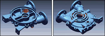
Figure 9. Pump housing scan data.
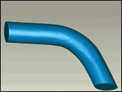
Figure 5. Preferred autofill of hole.
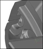
Figure 1. STL file appears correct.
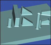
Figure 8. Fillets added to scan data.
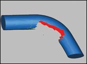
Figure 3. Typical hole to fill.
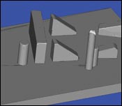
Figure 7. Scan with missing data filled in.
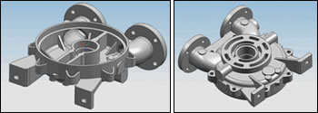
Figure 10. Resultant parametric solid model created from scan data.
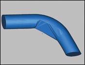
Figure 4. Non-preferred autofill of hole.
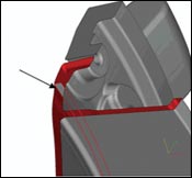
Figure 2. STL file with internal face.
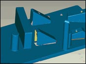
Figure 6. Typical scan data.
Interoperability among CAD systems has been an issue as long standing as CAD systems themselves. Prior to CAD, you were ensured of a relatively unambiguous exchange of part design by handing suppliers a hardcopy drawing. With the exception of some of the nuances of blueprint reading, everyone was literally on the same page.
With the proliferation of multiple CAD software packages throughout the industry, the exchange of geometrical information has become more complex. Initially, a neutral file format such as IGES (Initial Graphics Exchange Specification) served as an acceptable vehicle to bridge this gap as early CAD systems were somewhat simple with not much more than 2-D capabilities. However, with the growth of 3-D or solid modeling, this exchange needed advancement as well. Thus, new standards were developed such as STEP (Standards for The Exchange of Product model data), which included the ability to translate solid to solid information.


So how did you know if you got a good translation? Other than trusting the developers of the translator software, one quick check is to compare the volumes and surface areas of the before and after part. They won’t be exactly the same, but they should be to within a certain number of decimal places. This provides a quick check to make sure nothing major was missed in the translation.
Advances in Exchange Formats
Despite the advancement in exchange formats, they were, and still are, far from perfect. While many of these translation shortcomings can be bypassed by end users who simply knew that a “hole” in their data meant a fillet did not translate, for instance, the emergence of additive fabrication—rapid prototyping or RP—systems did not have that luxury. A good, “airtight” solid model of the part was needed, so a good translation from whichever CAD system the customer was using was absolutely necessary.
Another neutral format was developed specifically for RP systems called STL (many users have their own interpretation of what STL stands for, but it was initially developed for the first additive RP system developed by 3D Systems called StereoLithography).
The STL format is simply an approximation of the CAD system’s surfaces and faces using a series of connected triangles. Different CAD systems, however, tend to process this information differently. The CAD system's interface to this file format depends greatly on the validity of the solid or surface model. Some CAD programs allow the creation of STL files from surface (sheet body) models without having a legitimate solid body. This presents some problems to the additive fabricator as the STL file may require repair prior to attempting the build.
While some of the larger RP shops or departments have access to CAD software that may be used to create their own STL files or designs, many of the smaller ones require that the STL file be provided in order to create the part. Access to Unigraphics, ProEngineer, CATIA, AutoCad and SolidWorks can help circumvent any translation errors that may occur, but a suite of software to repair or manipulate files on the STL level also is good to have on hand.
Applications
Each STL file should be inspected thoroughly to ward off any potential problems with the actual build on the machine. For example, Figure 1 shows a portion of a STL file that correction software says is fine. However, if we remove the end face (Figure 2) we see a hidden surface within the part. This may build without any problems if the fabricated model is built solid, but for an investment casting pattern that is mostly hollow, this could present a problem with the model closing off a volume that is supposed to be continuous.
Contour Filling
Other areas to consider when repairing STL files are contour filling. If you have a contoured hole like in Figure 3, older or automated STL repair programs may have simply filled in the hole without regard to the surrounding surfaces (Figure 4. More sophisticated programs take into account the surrounding geometry to properly fill in these holes (Figure 5).
Optical Scanning
A fast growing area of technology presenting a new challenge for additive prototyping systems is laser or optical scanning. Some applications include reverse engineering existing parts, inspection or analysis of parts back to defining CAD geometry, or fixture design. Here, you can use white-light scanning, which is a line-of-site camera type system.
Inherently, you will receive scans with lots of holes in areas that simply can’t be seen, did not have enough shots taken or blocked out by fixturing. Again, for most downstream applications like inspection or analysis this is not a problem, but more and more, we are being asked to produce STL files and models or fixtures from these scans. Once again, we need to create airtight models out of data that just isn’t there.
Figure 6 shows some data from a typical scan. Combinations of software were used to make the repairs necessary for creating a buildable STL file. Some combination of hole fill and repair utilities were used to create the model shown in Figure 7. Additionally, extra fillets will be added in a part like this to increase its strength (Figure 8) using a freeform modeling software package that allows you to add fillet-type geometry to STL files.
Other applications for scan data requires the creation of a complete solid model that can be used in CAD system applications. Figure 9 shows a couple views of scan data of a pump housing. As you can see, some of the holes in the scan data are simply too large to fill this data in; therefore, we must re-construct the design intent. For this application 3-D scanning software technology was used to reverse engineer the parametric solid model shown in Figure 10, which was able to be used not only for additive fabrication prototypes, but for CAD system engineering and analysis as well.
Summary
An effective strategy is to have a number of different software tools available to aid in the problems that occur with system interoperability. With so many different customers and suppliers, you should maintain a number of different CAD systems to try and stay as “native” as possible when it comes to exchanging part geometry electronic information. When it comes to additive fabrication of these parts, rely on a number of different software programs to ensure you are able to create quality, accurate and sophisticated models with whatever data the customer has supplied.


Related Content

A 3D Printing Retrospective
A personal review of the evolution of 3D printing in moldmaking throughout the past 25 years.
Read More
The Benefits of Vertically Integrating Metal 3D Printing and Machining
Having 3D printing and machining within one organization enables Addman’s engineers to collaborate and consolidate so it can quickly make successful metal 3D-printed parts.
Read More
How to Supply Cooling to Additive Tooling
Additive tooling provides limitless options for cooling a mold’s difficult-to-cool areas.
Read More
Evaluating Metal Powders for Conformally Cooled Mold Inserts
Mechanical properties and design software techniques reveal the benefits of a modified high thermal conductivity metal powder for 3D printing in moldmaking.
Read MoreRead Next

How to Use Continuing Education to Remain Competitive in Moldmaking
Continued training helps moldmakers make tooling decisions and properly use the latest cutting tool to efficiently machine high-quality molds.
Read More
Reasons to Use Fiber Lasers for Mold Cleaning
Fiber lasers offer a simplicity, speed, control and portability, minimizing mold cleaning risks.
Read More