
Bridging the Gap between Part and Mold Development
Moldmakers need design automation, modeling and surfacing tools to facilitate effective interaction with product designers.


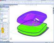
These images demonstrate how a 3-D CAD system that includes advanced surfacing capabilities provides moldmakers with the surfacing tools they need to more efficiently create molds for producing complex geometric designs.
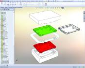
These images show how a flexible, parametric 3-D CAD system can give moldmakers the tools they need to import, diagnose, and repair diverse types of CAD data; evaluate part moldability to identify potential production issues; and address part design changes more efficiently.
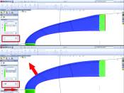
A 3-D CAD system can help moldmakers automate the creation of mold features for handling intricate part design features, such as the lip and groove feature shown in these images. Images courtesy of Solidworks.
In a global marketplace where competitive bids are just as likely to come from across the world as from across town, moldmakers face an increasing number of challenges that impact virtually every facet of mold development. Shorter leadtimes, pricing pressures that push down profit margins, and demands for higher levels of quality and longer duty cycles have substantially altered the paradigm for winning in today’s moldmaking industry. Producing molds faster, cheaper and better is the current mantra for moldmaking success, and moldmakers are continually evaluating mold design tools and technologies that can help them achieve these goals.


Communication Is Key
Examining the mold development process itself is equally important for determining how specific tools and development platforms can benefit a moldmaking operation. Such an assessment will reveal a fact that most moldmakers already know: the single aspect of the mold development process with the most potential for time- and money-saving productivity gains is the interplay between moldmakers and part designers. It’s this back-and-forth interaction between the customer who designs the part and the moldmaker who has to create the mold to produce it that holds the greatest opportunity for realizing the improved efficiencies moldmakers need to save time, reduce costs and maximize profits.
Although some manufacturers follow a concurrent strategy that encourages part design with an eye toward mold development, part design and mold development are typically separate, sequential processes for the vast majority of products. From the initial handoff of the part design to the moldmaker through evaluation of moldability, changes related to production issues, estimating, quoting and incorporation of in-process design changes from the customer, the interaction between part designers and moldmakers is a highly iterative process that is fraught with opportunities for delay and unanticipated cost. An easy-to-use, flexible 3-D CAD system that includes design automation/communication, parametric modeling and surfacing/geometry manipulation tools can bridge this gap—providing maximum benefits to moldmaking operations.
Handling Diverse Data, Geometry and File Types
The first step in the mold development process—responding to a request for proposal (RFP)—requires moldmakers to import, diagnose and repair part geometry in order to assess its suitability for injection molding, develop estimates and produce a formal quote. Because moldmakers need to complete this step before even winning the business, it behooves them to accomplish this as quickly and cost-effectively as possible by using a 3-D CAD system with broad model import and geometry manipulation capabilities. Of course, the best scenario is to use the specific CAD package that most of the moldmaker’s customers use to design parts, so the mold designer can simply open the file. However, because customer parts can range from 2-D drawings and neutral file formats—such as DXF™, DWG, IGES, STEP, ACIS® and Parasolid®—to file formats that are native to specific 3-D CAD systems, using a CAD platform that can import the widest set of diverse data formats directly, or through file conversions, provides a real advantage.
Whenever a mold designer imports plastic part data, he or she will inevitably encounter model geometry that includes errors, especially when converting or translating files. While a CAD system that can automatically diagnose and repair these errors is a real plus, mold designers will frequently need to repair some models manually. In these cases, using a CAD system that offers feature recognition tools for imported geometry can be a big help.
In addition to offering capabilities for diagnosing imported geometry in states of disrepair, CAD systems that include tools for repairing geometry errors have become increasingly beneficial. For example, mold designers need the ability to remove rounds and re-trim edges after removing rounds, especially when adding draft to improperly drafted parts. Moldmakers also may encounter complex model geometry with gaps in surfaces, for which they will need advanced surfacing capabilities, such as an n-sided surface patch, which allows mold designers to fill in a surface tangent to a space defined by any number of boundaries, or the ability to pull on a point in a network of curves to modify a surface. At minimum, mold designers need access to round, draft and surfacing capabilities (e.g., sweep, loft, etc.) to handle imported models of varying degrees of complexity more efficiently.
Automating Mold Development, Evaluation and Communication
Once a mold designer has imported and repaired part geometry, moldmakers can save additional time and reduce the volume of back-and-forth communications by using a 3-D CAD package that automates the process of creating a mold model for the part, evaluating the moldability of the part, and communicating design change recommendations to the customer, before finalizing the proposal. These kinds of capabilities can condense the time and effort required to achieve the baseline mold on which the proposal is predicated, as well as enhance the accuracy of the proposal in comparison with the final production mold.
In most cases, mold designers use the part geometry to design the cavity and core for the mold by applying a shrinkage factor to the part based on its material. Look for CAD packages that can automate the tasks typically associated with developing a mold model from the part, such as suggesting the optimal parting line based on the direction of draft within the part, rectifying areas of insufficient draft by expediting draft angle correction, and generating parting surfaces for molds, either automatically for simple molds or by providing the modeling and surfacing tools necessary for creating parting surfaces manually for complex molds. Can the CAD package conduct undercut analysis to pinpoint captive areas that may require sliders, lifters or cores? Can the designer check part wall thicknesses to address areas that are either too thick or too thin? Does the design platform automate the modeling of inserts, cores and pins, as well as the side core and lifter geometry required to extract finished parts from molds?
These capabilities can help moldmakers accelerate interrogation of the part, identification of necessary changes based on potential production issues, and development of the optimal mold to produce the part at volume. Access to design communication tools that enable moldmakers to communicate these findings to part designers quickly, inexpensively and effectively can further facilitate this process—documenting and resolving production issues prior to the actual submittal of the proposal.
Accelerating Design Changes
The last and perhaps most time-consuming interaction between moldmakers and part designers involves customer-driven design changes that occur after acceptance of the proposal yet prior to actual production. Almost without fail, moldmakers will have worked out any moldability problems and be well on their way to cutting a production mold when the customer sends along a design change. In the past, these type of late modifications—whether emanating from an engineering change order (ECO) or a simple marketing-driven change in aesthetics—could create both delays and cost overruns because of the amount of time and effort required to update all of the mold components to address the change.
With today’s parametric 3-D CAD packages; however, mold developers can tie interrelated components together, so if the part changes, the related components—the mold components in this case—will change and update accordingly. Whenever a customer sends along a new CAD file that incorporates a required change, moldmakers can simply import the model into the original part design and use it to automatically update the mold design. This approach not only saves time and effort, but also eliminates the possibility of making costly mistakes to account for the change. Using a parametric 3-D CAD system, changes made anywhere in the process automatically update all mold models and documentation, including parts, assemblies and drawings.
Summary
Today facilitating effective interaction between mold developers and part designers has become a critical factor for success. Iterations between moldmakers and customers remain vitally important for sorting through production issues and delivering effective production molds. By employing an easy-to-use, flexible 3-D CAD system that offers design automation/communication, parametric modeling and surfacing/geometry manipulation tools, moldmakers can shorten the time and reduce the effort associated with these iterations and effectively bridge the gap between part and mold development.


Related Content

Mold Builder Uses Counter-Intuitive Approach for Mold Challenges
Matrix Tool Inc. answers customers’ hard questions with creative solutions for cavity spacing, tool sizing, runner layout and melt delivery that reveal the benefits of running in a smaller press size at lower cavitation but higher yield.
Read More
Making Quick and Easy Kaizen Work for Your Shop
Within each person is unlimited creative potential to improve shop operations.
Read More
MMT Chats: Marketing’s Impact on Mold Manufacturing
Kelly Kasner, Director of Sales and Marketing for Michiana Global Mold (MGM) talks about the benefits her marketing and advertising, MGM’s China partnership and the next-generation skills gap. This episode is brought to you by ISCAR with New Ideas for Machining Intelligently.
Read More
From Injection Mold Venting to Runnerless Micro Molds: MMT's Top-Viewed June Content
The MoldMaking Technology team has compiled a list of the top-viewed June content based on analytics. This month, we covered an array of topics including injection mold venting, business strategies and runnerless micro molds. Take a look at what you might have missed!
Read MoreRead Next

Does Your CAD System Support Design and Validation In One Window?
Implementing one tool that can handle part design, mold design, part structural analysis and mold filling analysis is becoming a necessity for today’s mold shops.
Read More
How to Use Continuing Education to Remain Competitive in Moldmaking
Continued training helps moldmakers make tooling decisions and properly use the latest cutting tool to efficiently machine high-quality molds.
Read More
How to Use Strategic Planning Tools, Data to Manage the Human Side of Business
Q&A with Marion Wells, MMT EAB member and founder of Human Asset Management.
Read More