
Breaking the Mold in Mold Development
Integrated analysis capabilities streamline mold design.
Share
Read Next


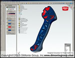
Engineers can use integrated finite element analysis (FEA) software to validate design performance and avoid wasted rounds of tooling development. In this example, Dimonte Group engineers used analysis software integrated directly inside CAD software to optimize snap fits on a perfect dose pool developed for Stellar Manufacturing Co. Instead of making molds, trying them out, then reworking the tool to dial in the correct snap force, engineers ran analysis studies to achieve the correct force, avoiding tool rework costs.
Undercut analysis capabilities enable engineers to identify features such as undercuts, tabs and lips that may require the development of molds that involve side actions. Dimonte Group engineers used this software to identify undercuts in this handle, which they developed for Prince Castle, Inc.

Integrated mold fill analysis capabilities allow engineers to simulate the filling of a mold so they can avoid warp, bubble and sink issues. In this case, The Dimonte Group used mold analysis software that is integrated with CAD software to confirm proper filling of the mold after knit lines were relocated in a dual condiment dispenser for McDonald's.
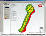
Designing parts with sufficient draft ensures that parts will eject or pull out of the mold without sticking. Here, Dimonte Group engineers used draft analysis capabilities to identify where draft adjustments were necessary in the design for this handle, which they developed for Prince Castle, Inc.
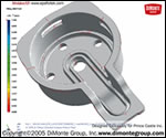
An integrated mold analysis tool can help designers identify and address potential knit line problems. Here, engineers from The Dimonte Group used mold analysis software that is integrated with CAD software to resolve knit line issues in a dual condiment dispenser for McDonald's. The knit lines coincided with the witness marks where the mold closed, creating an area of high stress that led to failure. The engineers moved the locations of the knit lines to solve the problem.
Today's sleek and stylish consumer products increasingly require some form of mold to produce, and many leading manufacturers have discovered they can save time and money upfront by using design analysis tools that are tightly integrated with CAD systems.
Whether designing a mold for a hand-held device, such as an iPod, or for larger components, such as a refrigerator door, engineers can take advantage of integrated design analysis tech-nologies to avoid the delays and costs associated with traditional trial-and-error approaches to mold development. Discovering problems after investing the time and money to create molds and cut tooling is a nightmare both for the product developer and moldmaker. As a result, most moldmakers have begun to use some sort of design analysis tool.


Many design analysis tools, however, are not tightly integrated with CAD systems. Rather, they require the painstaking transfer of design data from the CAD system to the analysis application, which wastes time, increases the risk of error and opens a communication gap between product designers and moldmakers. Leveraging analysis tools that are tightly integrated with a CAD system—whether those tools are part of the base CAD package or add-on applications—represents a far more efficient and reliable approach for producing viable molded parts that move quickly to market.
Integrated design analysis tools for moldmakers fall into three general categories:
(1) Mold analysis capabilities that are part of a base CAD package.
(2) Tightly integrated finite element analysis (FEA) systems that validate part performance.
(3) Specific mold-flow applications for ensuring proper filling of plastic resins within the mold that function as an integrated extension of the designer's original CAD-generated design.
A 3-D mechanical design system—with draft and undercut analysis capabilities as part of the base CAD package, integrated analysis software addressing FEA validation needs and integrated partner add-on applications that support higher-end mold-filling analysis requirements—is an example of a CAD environment that includes or supports the tools explained in the three general categories. This broad range of integrated tools enables engineers to design and validate both the part and the mold, allowing them to address a wide range of potential moldability problems—including draft, undercuts, part strength, sharp corners, warping, bubbles, sinks and non-uniform wall thicknesses, without having to leave their familiar design environment.
Ensuring Sufficient Draft
Designing parts with sufficient draft—the angle between the direction of ejection of the part from the mold and the surface of the part—is critical for ensuring that parts eject or pull out of the mold without sticking. The degree of draft guidelines vary depending on the part geometry, surface characteristics, fill material and mold type (e.g., straight pull, side actions, etc.). But in most situations, two degrees of draft works well.
Engineers can assess draft while designing the part in CAD systems by using the inherent draft analysis capabilities available in better mechanical design offerings. In some software, running a draft analysis will highlight any faces of a part that need additional draft so designers can adjust the draft on the solid model before production.
Undercut Analysis
Many consumer products include features such as undercuts, tabs and lips that may require the development of molds that involve side actions. Too often, designers do not discover these special requirements until they first interact with the moldmaker, which can add an additional round of costly design changes to the process.
By using a CAD system with internal undercut analysis capabilities, color codes help designers easily identify regions of a part that may require side actions. Engineers can then decide whether to include these features in the part or modify the design to reduce the cost and complexity of the mold. In either case, undercut analysis capabilities enable designers to make any required changes upfront, streamlining subsequent interaction with moldmakers and tooling vendors.
Part Performance
Producing injection-molded parts that function poorly is perhaps the leading cause for wasted rounds of tooling development. In the past, engineers often did not discover design flaws in parts—such as stress cracks and other failures—until they had actually produced the molded part, and many manufacturers historically used prototype molds to validate design performance. This approach added an additional step to the design cycle with attendant costs and delays.
With integrated FEA capabilities, designers can detect and address potential performance flaws within their CAD systems during the initial design stage, when changes are easiest and least costly to make. For example, FEA can identify stress risers in part corners that hinder plastic flow, and engineers can use radii to round the corners, distribute stresses and streamline the flow of molten plastic. Snap-fits are another common analysis application. Using integrated FEA capabilities, designers can optimize the appropriate snap force before the mold is made, thereby avoiding repetitive prototyping and tool rework.
Controlling the Impact of Knit Lines
Two separate plastic flows coming together in a mold produce knit lines, which can range from invisible to a clearly visible raised seam—depending on the resin, temperature and filling speed. For aesthetic reasons, moldmakers strive to either minimize the knit line's prominence or hide it on the backside of parts, such as housings.
In addition to the cosmetic considerations, knit lines can create an area of weakness in a part that results in failure, especially when the knit line is located in an area of high stress. Integrated FEA capabilities can reveal areas of high stress, and an integrated mold filling application can predict where the knit lines will form. With this information, designers can make design changes in the software that relocate knit lines into areas of low stress. They also can experiment with different materials to make knit lines as unnoticeable as possible. Controlling the impact of knit lines during early design eliminates the potential for costly, time-consuming surprises during production.
Avoiding Bubbles, Warps and Sinks
Integrated mold analysis also helps engineers optimize wall thicknesses and eliminate voids, surface flaws and other part distortions. As plastic resins solidify in a mold, they freeze or firm up from the outside (near the mold surface) inward. In thick-walled parts, this behavior creates inward-pulling stresses related to contraction that can cause bubbles, voids and sink marks in the outer surfaces of the part. Conversely, thinner-walled sections will solidify more quickly. This disparity creates the possibility that stresses will build up between the thick and thin sections, which can cause the part to warp. Using thin ribs on thicker walls also can create sinks in the wall, and designers can avoid this common problem by making the ribs at least half as thick as the wall they support.
While uniform wall thickness is the ultimate goal, there are cases where the designer cannot get around having walls of varying thicknesses in a part. With a design environment that supports an integrated mold filling analysis package, designers can evaluate the interaction between thinner and thicker portions of the part and optimize wall thicknesses to eliminate voids, sinks and warps.
Unique Circumstances
Because the physics of injection molding are so complex, new situations entirely outside the norm can arise for which integrated analysis capabilities provide the necessary tools for a solution. A particularly interesting example involved the design for a long, flat, injection-molded part that would cup (deform inward) as it cooled. Mold flow analysis showed that no matter how the designer gated or cooled the part, it would cup in a direction that made it non-functional.
Using new features in CAD software, the designer solved the problem by bending the part model in the opposite direction, intentionally deforming its shape, so as the part cooled it would unbend into its intended flat shape. This case illustrates how using a design environment with integrated analysis capabilities can help engineers gather information to solve moldability problems that would otherwise be virtually unsolvable.
This is a far cry from the outdated trial-and-error approach. By using a design environment that provides access to integrated tools for mold design and validation, engineers can work more productively, reduce costly errors, avoid lengthy delays, and remove communication barriers between product designers and moldmakers. As a result, new, less costly products move more quickly to market, giving the designer and moldmaker a heightened role in the organization's success.


Related Content

Tolerancing in Mold Design, Part 1: Understanding the Issues of Conventional Bilateral Tolerancing
Mold designers must understand the location, orientation and form limitations of conventional tolerancing before changing to another dimensioning system.
Read More
Products and Services for Multiple Moldmaking Needs
New year, new technology roundup! Featured here is a collection of product offerings, from profile milling cutters to industry-specific CAD/CAM software to innovative hot work tool steels.
Read More
MoldMaking Technology's Most-Viewed Content 2022: Products
MMT shares the five top-viewed technologies, equipment and services of 2022 in each Engineer, Build, Maintain and Manage tenet based on Google Analytics.
Read More
The In's and Out's of Ballbar Calibration
This machine tool diagnostic device allows the detection of errors noticeable only while machine tools are in motion.
Read MoreRead Next

Using CAD Data to Build Molds By the Numbers Can Reduce Costs and Leadtime
Crucial initial decisions must be made before machining begins.
Read More
How to Use Strategic Planning Tools, Data to Manage the Human Side of Business
Q&A with Marion Wells, MMT EAB member and founder of Human Asset Management.
Read More
Are You a Moldmaker Considering 3D Printing? Consider the 3D Printing Workshop at NPE2024
Presentations will cover 3D printing for mold tooling, material innovation, product development, bridge production and full-scale, high-volume additive manufacturing.
Read More