
Becoming More Accurate With Speed
By adding optimization software to their machining, moldmakers will be able to produce better quality parts with better accuracy.


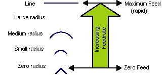
Figure 3: Over-travel.
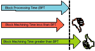
Figure 2: Block processing time problems.
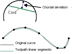
Figure 1: Chordal deviation.
The key to everything is accuracy. During the moldmaking process every job that is performed when building a mold and every task completed by a machine builder or high-speed control manufacturer is centered on accuracy. Finding a better way to become more accurate during the machining process is one of the moldmaking industry's ongoing missions.
When introduced, CNC machines were machining relatively simple 2-D shapes, which were represented by lines and arcs that were programmed by hand. With lines and arcs as the primary entities, the accuracy of the final part was controlled by the accuracy of the machine and the ability of the control to follow the instructions that it was given - not the data.


CAD/CAM systems then appeared, which at first were used to speed up the hand programming to reduce the amount of human error. They were still making 2-D shapes. Soon, CAD systems started dealing with curves and surfaces. This was a new ball game, especially for the CAM side of the equation. It was no longer a simple question of offsetting lines and arcs with perfect mathematical accuracy. The toolpath, which was needed to machine the curves and surfaces, could not easily be defined in these terms. So, they did the next best thing - they made the toolpath "mostly" accurate or more precisely, accurate to within a specified tolerance. This amounted to representing the curves with a series of linear segments, which approximated the theoretically perfect curve. These linear segments are usually made based on a chordal deviation (see Figure 1).
| Chord - a chord is a line, which intersects an arc (or curve) at two points.
Chordal deviation - the chordal deviation is the maximum distance between the chord and the arc (or curve). One of the benefits of using a chordal deviation to control the tolerance of linear segments is that you have a consistent deviation. If you simply break a curve into equal length lines, the deviation of the lines from the curve would change, as the curvature became larger and smaller. Using a chordal deviation also results in a smaller data set than other methods of linearization with similar tolerances. |
The Problems
At this point, we had an approximately correct data set, but a whole new set of problems came to light. The first problem was a control - which was designed to cut long lines and arcs - unable to cut thousands of small lines efficiently. It would literally choke on the data because of block processing times (BPT), which were too slow. This problem manifested itself as a stuttering or shaking of the machine tool - and anyone who has tried to cut a mold on a machine without an extremely fast high-speed control knows what this behavior looks like (see Figure 2).
| Block Processing Time (BPT) - The time it takes for a control to read a block of code, (i.e.: G1 X5.9876 Y3.9874 Z2.5467 F150.) understand the block of code, send the appropriate instructions to the servos, reset, and begin to read the next block of code.
Block Machining Time (BMT) - The time it takes for a machine to physically move to the end of the programmed block of code. The best way to understand the cause of these problems is to view them as the relationship between the Block Processing Time (BPT) and the Block Machining Time (BMT). If the BMT is longer than the BPT, everything will run smoothly. If the BMT is shorter than the BPT, there will be problems when the machine reaches the end of the given instruction and the control has not had time to decide what new instructions to give to the servos. The machine must pause (also known as "Servo Starvation") while it waits for the next instruction. This manifests itself as a stuttering or shaking as the process is repeated over and over. What can be done about this problem? 2. Increase the physical length of each instruction. 3. Decrease the BPT. |
CNC programmers learned to alleviate the block processing time problem by slowing feedrates or by making less accurate toolpaths - neither of these were good solutions. Slowing the feedrate caused exceedingly long machining times and reducing the toolpath accuracy increased the handwork required to bring the part to an acceptable finish - not to mention making a less accurate part!
Finally, along came high-speed controls to the rescue! High-speed controls were designed to reduce the block processing time to a minimum. As the block processing times became shorter, CNC programmers were free to run higher feedrates and to make more accurate files in the form of smaller lines to define the curved surfaces. The shorter the block processing time of the control, the faster you could machine and the more accurate you could make the data.
| Over-travel involves machining away from the desired data in the toolpath. In other words, machining inaccurately. This is caused by moving too fast relative to the curvature of the part. This is really just a basic physics problem, which is controlled by the following factors:
1) The rate of direction change (the degree of curvature). In simpler terms, you can think of the rate of direction change as the curvature. If you were thinking in terms of circles, a circle with a one-inch radius has a smaller curvature than a circle with a two-inch radius, and the rate of direction change is quicker on the one- inch circle than on the two-inch circle, on the other hand, a line has no direction change. The second factor, the force, is the servo drive motors on each of your machine's axis. They have a finite amount of force available to apply to each axis. To be more accurate each axis is a linear axis, and what we are really saying when speaking of a single axis and servomotor is "how much force is available to accelerate or decelerate." The larger the servomotor, the faster you can accelerate or decelerate a given mass. The third factor is the mass. This includes the part, and on a bed type mill, the tables. It's interesting to note that on most bed type mills, one of the axes moves two of the beds. This means one of the axes has a lot more mass to move. This is usually the axis that controls the maximum acceleration and deceleration of the machine tool. If you insist on a formula, it's the old standard formula F = MA where Force is the servos, Mass is the tables and the part, and the Acceleration is relative to the curvature, because the smaller the curvature, the more acceleration (deceleration) is required to slow down to accurately cut the curve without leaving the programmed toolpath. The thing to remember about all of this is that the only one of the three factors that changes on a given machine is the curvature. The machine always has the same servos, and it is moving roughly the same mass. This means that any given curvature on any given machine has a particular feedrate, which will accurately cut a particular curvature. We'll call this the "accurate feedrate." The accurate feedrate is faster on large curvatures and slower on small curvatures. On straight lines the machine can move at rapid rates accurately, but on sudden direction changes (sharp corners) the control must stop if it is to be completely accurate. |
The story is not complete. With the advent of the ability to machine at very high feedrates, a new problem developed - over-travel (see Figure 3). True high-speed controls limit the over-travel by varying the feedrates relative to the curvature of the part. They do this based on tests conducted when the high-speed control is integrated with the machine tool. This test data is incorporated into a formula, which correlates the correct feedrates with the physical capabilities of the machine tool to maintain a specified accuracy as the curvature changes.
Even this feedrate control was not enough to guarantee the accuracy of the machining process. The next barrier was the ability to "look-ahead" to see what curvatures would need to be machined later in the toolpath and what feedrates should be used to control the accuracy. Due to the thousands of small points in the toolpath, the control needed to have the ability to consider what was required many blocks ahead of its current position. If the control couldn't see what was coming up, it might be traveling too fast to slow down to the "accurate feedrate" when it reached a small curvature.
On a modern mold there may be many small linear moves between the point to begin deceleration and the point where the feedrate must be slower. Suppose there were 70 blocks (little lines) between the point to begin deceleration and the point at which the feedrate must be slower. If the control is only able to calculate the correct feedrate for the next 20 blocks, then it will already have traveled past the point where it needs to begin to decelerate before it realizes that there is an area of small curvature approaching. The result is over-travel.
You have seen that true high-speed controls have the following required features:
1) Fast block processing;
2) Accuracy control (by adjusting the feed relative to the curvature); and,
3) Large look-ahead capability.
Without each of these features, it is not a true high-speed control. Interestingly, when you look at the history you begin to realize that all of this arose from the need for better accuracy.
How Accurate Is Good Enough?
Why do we really need to be so accurate and how accurate is "good enough?" The main reason that you should be concerned about accuracy is that there is no other way to get a good finish on your part. This cannot be over emphasized. Poor finishes are the result of poor accuracy somewhere in the process. There are two places that the accuracy must be controlled. The first place is the data (the toolpath) and the second is the CNC machine.
Data
When you machine a complex shape, you are machining many passes - one right next to the other. If these passes are not accurate - one pass may be high and the next pass may be low relative to each other - the result is a poor finish. The more accurate the data is, the less likely this will be the cause of your finish problems.
A valid question is, "How accurate should my data be?" The answer is actually very straightforward. To get the best possible results from your machine tool, your data should be slightly more accurate than your machine. If your machine can hold an accuracy of .0005" then you should make the total of all tolerances in your toolpath add up to a number no greater than .0005". For many machines, this will produce such a large number of short line segments that the block transfer time of the control will become a problem, but we are coming to the solution for this. Now, keep in mind that if your data is more accurate than your machine, the data cannot add to any finishing problems.
Machine Tool
The machine is comprised of two major parts - the control and the machine itself. As for the control, this is precisely the reason high-speed controls were developed. They allow the machinist to increase the accuracy of the parts he/she is machining and subsequently to make a higher quality part, with less handwork required.
In the case of the machine, accuracy depends on a multitude of things, like the ability to know the actual position (encoders and scales), the accuracy of each of the parts of the machine (ball screws, ways, tables, etc.) and the rigidity of the machine - just to name a few. You should keep in mind that if all else is equal, the most accurate machine will make the best finish on your parts.
One of the interesting side notes to all of this is that high-speed machining is the functional equivalent of "accurate machining." High-speed machines were really made to be accurate. The fact that they are fast is in some ways a by-product of being accurate. Before high-speed controls were introduced to the mold and die industry, the limiting factor to machining time and quality was typically the control. More specifically, it was the block transfer time of the control. Because of this, the physical limits of the machine were never reached while machining complex shapes. With the advent of true high-speed controls, the control was suddenly ahead of the machine and the machine manufacturers were forced to build a better machine to take advantage of the higher accuracy and speed provided by the new controls. A good, integrated high-speed machining center with a high-speed control defies finding a specific factor, which limits more accurate and faster machining. This is specifically because the control and the machine are a fine balance of capabilities.
So, what happens if you put a high-speed control on a regular machine? Well, what happens is that for the first time you start to reach the physical potential of your machine tool - before the retrofit you were limited by the control. The key words are the "physical potential" of a particular machine. You will never make a regular machine capable of the same high accelerations (short machining times) while maintaining accuracy as a good high-speed machining center. However, as long as the machine is not worn out, you can still get a very good finish when you start to truly control the error. This is where machine build becomes important, because the better the machine is built, the higher accelerations it can withstand and the more accurate it can machine any particular part. In other words, you can make a better part faster with a machine, which is built better, if you can eliminate the control as the limiting factor.
Overcoming the Problems Using Machine Optimization Software
Machine optimization software will help you get the full potential from all of your machine tools - both old and new. The use of this software will be discussed as it relates to machines without true high-speed controls and then how it relates to those with true high-speed controls (see Figure 4).
| Figure 4: Overcoming problems using machine optimization software. | |||
| Problem | Solution | Solution with Machine Optimization Software | Result |
| BPT problems due to many short linear segments. | Put a fast CPU on the control to reduce the time to calculate each block of code. | Longer and fewer entities which enables a slow control to process the information. | No BPT problems. |
| Over-travel as the result of curvature changes. | Machine-specific feedrates relative to the curvature of the toolpath. | Machine-specific feedrates relative to the curvature of the part and "Exact Stop" insertions. | High-accuracy cutting with low strain on your CNC machine. |
| Large look-ahead in order to begin decelerations in time for curvature changes. | Put a fast CPU on the control to process far ahead of the current position. | Greatly reduce the number of blocks, allowing a small look-ahead to be adequate. | No over-travel caused by the inability to see impending curvature changes in time to decelerate. |
Machines Without High-Speed Controls
As discussed above, CNC machines without high-speed controls are typically limited by the control. The first problem is the block processing time (BPT). The key to defeating BPT is to make the block machining time (BMT) longer than the BPT time. This can be done in one of three ways:
1) Slow the feedrate.
2) Increase the physical length of each instruction.
3) Decrease the BPT (retrofit a high-speed control).
Optimization software uses the second method and accurately fits arcs to the point-to-point data produced by the CAM system. One arc often replaces more than nine out of 10 lines with a single arc - even at extremely small tolerances. This means that the physical length of each block is longer. With longer blocks the BPT of the control can be much slower without inducing the stuttering or shaking problems caused when the BMT is shorter than the BPT.
How much slower can the control be? Well, in the case where optimization software replaces nine out of 10 blocks of code with a single block, the control can be 90 percent slower at similar tolerances. Or a better way to look at this is that you can make a much more accurate part before the BPT of your control becomes the limit.
If all you wanted to do was go faster, it would be enough to make your tolerances larger in your CAM system. This would make longer and longer lines and help to alleviate the BPT problems. Anything which reduces the number of blocks, reduces the chances that you will have BPT problems. Unfortunately, this method also makes a very bad finish - and you want more than this, you want a better part. As you know, better finishes require accuracy.
With the great reduction in the number of blocks and the longer entities produced by optimization software, new problems arise. Making the controls fast was only the first step. You also need to control accuracy, which comes from two places - the data and the machine. Because optimization software virtually eliminates the BPT problem even from an older control, you can produce data more accurately than ever before without BPT problems. You also should remember that the correct accuracy for the data is something slightly better or equal to the physical capabilities of the machine tool. Without optimization software this was not possible because there was simply too much data and your control couldn't handle it; with optimization software as part of your process, small tolerances will be welcome on your control.
The second major factor which controls the accuracy of your part is the machine. When the strain is taken from the control, suddenly the mechanics of the CNC machine become the limit to how fast and accurate you can cut your part. With optimization software you can actually machine your molds and dies too fast. You probably wonder how you could possibly machine too fast. Isn't that good? No. Too fast results in over-travel, and over-travel means inaccuracy and inaccuracy means a bad finish.
Machining fast without controlling the error only makes a bad part faster! Many machinists don't realize that the small gouges they give to the polishing department to clean up are often not caused by bad data, but rather by over-travel. This is particularly true in areas of sudden direction change, like the area of a cavity where the tool travels from the floor of the cavity to the wall. The trick is to always maintain feedrates, which don't allow the machine to leave the programmed data in the first place. When you maintain an accurate feedrate relative to the curvature and the physical ability of the machine, you never will put your machine into an over-travel condition. An added benefit is that when you prevent over-travel conditions, you reduce the wear and tear on your CNC machine, and you will actually get better parts while extending the useful life of your machine tool. Optimization software will provide this machine-specific accuracy control.
Optimization software has the ability to be customized to individual machine tools and to produce feedrates, which will prevent over-travel and maintain accuracy. In fact, every arc produced by optimization software will get a unique feedrate, which is specific to your machine tool and its physical capabilities. Optimization software also will look for any sharp corners in the toolpath and insert the appropriate G-code to prevent the thumping and bumping so common in these areas. What this means to you is a more accurate part with substantially better finishes in a fraction of the time.
With optimization software you need to think a little differently about how you program your toolpaths. First, you can finally make more accurate toolpaths without the hassles. You also can program higher feedrates. Since optimization software controls the maximum feedrate at any particular curvature and because the BPT problems are virtually eliminated, for the first time you can analyze your part and program your feeds and speeds based upon the best case scenario on your mold or die. Your decisions for feeds and speeds are currently centered on the worst case scenario. Now, you must decide where your biggest problem area is (like the sharp transition from the cavity floor to the wall) and then program a feedrate, which only gouges a little in this area. The unfortunate part is that this means you are machining slower than needed everywhere else on the mold. Optimization software will allow you to program for the best case scenario, and then optimization software slows down only as much as is needed in all other areas to maintain an accurate cut. This difference in feed control alone can cut your machining time in half while producing a better finish. Imagine machining your entire part at the fastest possible accurate feedrate, instead of the feedrate that only gouges a little.
Although machining faster and making better parts on your current equipment sounds too good to be true - it isn't. Optimization software simply tackles the same problems that a high-speed control handles. There is practically a one-to-one relationship. Let's look at the problems again and then how both optimization software and a high-speed control solve these problems (see Figure 4).
A high-speed control accomplishes the tasks with raw computing speed, while optimization software does it with finesse, but the results are virtually identical. Optimization software is like retrofitting all of your machines with a high-speed control. There are, of course, differences - for instance, you only have to buy one copy of optimization software and it will work with all of your machine tools.
Do you want to know how to get the absolute best results? Combine optimization software with a good high-speed control.
Machines With High-Speed Controls
If optimization software does the same thing as a high-speed control, how can it help a high-speed control and a machining center? This is another excellent question. Let's start by analyzing what you get from a state-of-the-art, high-speed machining center. You get exceptional accuracy and speed. The machining center does exactly what it was meant to do - it follows the data that was provided within a specified tolerance. What tolerance? That's up to the OEM who put the control on the machine. This is part of the testing that is done when the control is integrated with the machine tool and the feed control "table" is entered into the control. The OEM can make this tolerance anything he wishes. It's a fine line he/she walks. If he/she makes it very accurate, the machine will have to cut slower in order to follow the data; if he/she makes it rather large, the machine will be able to travel much faster on the same data, but the finish quality will suffer. At least one manufacturer has made multiple feed tables (tolerance levels) available, so that the end user can select the desired accuracy versus machining time. You cannot have both - or can you?
The data from optimization software comes much closer to providing both a higher accuracy and faster machining than any other method. Optimization software is able to do this by providing data to the control and machine that lends itself to machining faster while simultaneously holding a high accuracy.
It does this in a number of ways. First, it provides large areas of constant curvature, which have no sudden direction changes requiring decelerations. Second, it reduces the total number of endpoints and consequently, transition points. Third, the remaining transition points have a much lower angular change.
The results of this are that the machine will typically reach higher feedrates along a cut and maintain them longer because it doesn't need to decelerate as frequently. This has been confirmed by independent testing at a major control manufacturer - and is in large part why the control manufacturers are currently pushing NURBS machining. Nevertheless, it really is very difficult to say how much time this will save on any given part. It will vary with the shape of the part, the size of the part and the maximum programmed feedrate. If the feedrate is programmed very slowly, you will see less time difference with and without optimization software. The faster the programmed feedrate and the smaller the error allowed by the control, the larger the time difference.
Finish quality also is improved because you can easily machine data that is more accurate than the machine without any problems. Furthermore, this data is represented with large areas of constant curvature with smoother transitions at the block endpoints.
In a nutshell, you get the best finish at the highest tolerance in the least amount of time by using machine optimization software.
Conclusion
Machine optimization software will help all machine tools to make better parts faster. If you are currently using a machine that does not allow you to cut high- precision data and does not control the error (over-travel) while cutting, optimization software can often double (or more) the throughput of the machine on finish passes. It can do this while providing the very best finish that your particular machine is physically capable of, which is much higher than you can imagine if you don't have optimization software.
If you already have a state-of-the-art high-speed machining center, optimization software can still help you, but it is more difficult to state how much time you will save. Customers currently using optimization software on high-speed machines report time savings as low as five percent on some parts and as high as 40 percent on others. Typically the range will be 15 to 30 percent, which is quite a bit on a machine that is already traveling very fast. You also will see an improvement in finish quality - even on a high-speed machine.
Here is a brief list of the major benefits of optimization software to your machining.
1) Better quality parts at higher accuracy.
2) Reduced machining time (on some machines three to four times faster).
3) Reduced polishing times (for many shops, it has eliminated polishing).
4) Reduced machine maintenance and longer machine life.
5) Reduced file transfer times to older controls (typically transfer in 1/4 the time).
6) Reduced storage problems (files usually fill only about 1/4 of the original disk space).
As you can see, optimization software works by simply doing a good job of making your toolpath data perfect for reaching the physical potential of your machine tool and control. Optimization software doesn't use any magic, just an understanding of the process and the various limits, along with the ability to overcome them.
In summary, good finishes require accuracy. The truly difficult thing to do is to produce accuracy and the shortest possible machining times - this is the entire purpose of machine optimization software.


Related Content

OEE Monitoring System Addresses Root Cause of Machine Downtime
Unique sensor and patent-pending algorithm of the Amper machine analytics system measures current draw to quickly and inexpensively inform manufacturers which machines are down and why.
Read More
How to Manage Wall Thickness Changes in Your Mold Design
To ensure even filling and cooling, consider wall section transitions, corners and fillets, ribs and bosses, lip and rim designs and CAE flow simulation software.
Read More
Products and Services for Multiple Moldmaking Needs
New year, new technology roundup! Featured here is a collection of product offerings, from profile milling cutters to industry-specific CAD/CAM software to innovative hot work tool steels.
Read More
The In's and Out's of Ballbar Calibration
This machine tool diagnostic device allows the detection of errors noticeable only while machine tools are in motion.
Read MoreRead Next

How to Use Strategic Planning Tools, Data to Manage the Human Side of Business
Q&A with Marion Wells, MMT EAB member and founder of Human Asset Management.
Read More
Reasons to Use Fiber Lasers for Mold Cleaning
Fiber lasers offer a simplicity, speed, control and portability, minimizing mold cleaning risks.
Read More
How to Use Continuing Education to Remain Competitive in Moldmaking
Continued training helps moldmakers make tooling decisions and properly use the latest cutting tool to efficiently machine high-quality molds.
Read More