
Balancing Considerations for High-Speed Machining
Many moldmakers utilize high-speed machining in their shops today, making balancing of the tool and toolholders a priority to preserve the integrity of the work and protect the investment in the equipment.


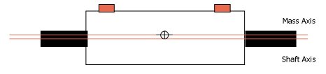
Figure 1: Static unbalance.
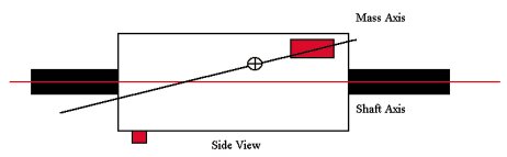
Figure 3: Dynamic unbalance.
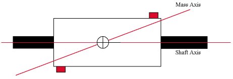
Figure 2: Couple unbalance.
High-speed machining is a fact of life in many machine shops around the world today. In industries such as moldmaking and aerospace, it has become the norm rather than the exception. One clear benefit of this trend is the achievement of greater efficiency and productivity through increasingly higher spindle speeds. However, as the spindle speeds of machining centers continue to increase, the potential for adverse effects to the machine and the workpiece due to vibration increases exponentially because centrifugal force increases with the square of the speed. One of the major contributors to vibration, and the easiest to control, is unbalance. Since the spindles on all machining centers are uniformly balanced to the appropriate ISO recommended levels, the major source of unbalance is the toolholder, as well as the tool itself.
Why Balance?
Vibration caused by unbalance has many well-known effects on the machining process. The most obvious is chatter. One common reaction to chatter is to reduce the spindle speed, which of course reduces the capability of the machining center. On the workpiece, the principal effect is poor surface finish and the inability to hold close tolerances. And on the machine you will get markedly poorer tool life and ultimately, over time, spindle and bearing damage is likely to occur. This latter fact is why many machining center manufacturers recommend balanced tooling and in some cases actually void the spindle warranty if balanced toolholders are not used above a certain speed. The threshold that defines high-speed machining for the purposes of balancing historically has been 8,000 to 10,000 rpm. However, there are a number of variables that affect this. This article will discuss in greater detail the spindle speeds at which toolholder balancing becomes critical.


Unbalance Defined
Unbalance is defined as "That condition that exists in a rotor when vibratory force or motion is imparted to its bearings as a result of centrifugal force." Unbalance is caused by an uneven distribution of mass around the axis of rotation of a rotating body. This can result from fixed as well as variable sources. The fixed causes of unbalance result from non-symmetry of design. In toolholders, this could be from the drive slots on CAT-type toolholders or setscrews in some milling cutter-type holders. The variable causes include material irregularities such as voids and porosity in the base material, operational factors such as distortion due to centrifugal force, and manufacturing tolerances. Unbalance in a toolholder causes displacement of the principal axis of inertia (mass axis) from the axis of rotation. When perfectly balanced, these axes are coincident.
There are three types of unbalance that have an effect on toolholders: static unbalance, couple unbalance and dynamic unbalance.
Static Unbalance
Static unbalance arises when the principal inertia axis is displaced parallel to the axis of rotation (see Figure 1). It can be compensated for by either adding or removing material equal in weight to the unbalance amount in a single plane, perpendicular to the axis of rotation. Static unbalance can be measured either on a rotating or non-rotating balancing machine.
Couple Unbalance
Couple unbalance exists when two equal unbalance masses are positioned exactly 180' apart in two planes perpendicular to the axis of rotation. This causes the principal axis of inertia to displace not parallel to but intersecting with, the axis of rotation at the center of gravity (C.G.) of the part (see Figure 2). A couple unbalance only can be corrected with another couple. That is, by applying correction equal and opposite to the original couple. It only can be measured on a rotating-type balancing machine.
Dynamic Unbalance
Dynamic unbalance is the most commonly occurring type of unbalance. It is the combination of static and couple unbalance. It causes the principal axis of inertia to deflect from the rotational axis both non-parallel to it and not intersecting with it at the C.G. (see Figure 3). Dynamic unbalance only can be corrected in two planes by adding or removing material. Like couple unbalance, it only can be measured on a rotational type balancing machine.
Unbalance levels and tolerances can be described in several ways, the most common being by stating the amount of weight required to correct the unbalance multiplied by the radius at which the weight is applied. Hence, units such as ounce-inches or gram-millimeters are used. Conversely, unbalance also can be defined as the amount of weight required to balance the part at a given radius (normally the O.D.). This is more of a process definition of the allowable residual unbalance in a part and is described as "X grams (or ounces) at the radius," for example. Unbalance levels also can be described by the amount of displacement of the principal inertia axis from the rotational axis as described above. The units used in this case are normally in micro-inches or microns (micro-meters). More on this topic follows.
Unbalance and Center-of-Gravity Displacement
The relationship between unbalance and center-of-gravity (C.G.) displacement is of great importance in understanding balancing. Take the example of a perfectly balanced disc weighing 999 ounces; then add a one-ounce mass at a 10-inch radius. The unbalance (U) can be found by multiplying the mass (m) times the radius (r).
U = m x r (1)
U = 1 oz. x 10 in. = 10 oz. in.
By definition, the weight of the disc is concentrated at the C.G. The unbalance mass tends to pull the C.G. away from the geometric center, causing a displacement called eccentricity (e) or:
U = W x e (2)
W = 999 + 1 = 1,000 oz.
By substituting the known values we can then solve for e.
e = U = 10 oz. in. = 0.01 in.
W 1,000 oz.
Correcting Toolholder Unbalance
In general, you can correct unbalance in a rotor by removing material at the "heavy spot" or adding material 180' from it. Most people can relate to adding material for balancing purposes by considering the lead weights used to balance tires. Overall however, removing material is the far more common method of balancing. Balanced toolholders can be purchased from many manufacturers of toolholding devices. As the name suggests, these are pre-balanced at the factory, generally by material removal. Obviously, the holders only are balanced. Once a cutting tool is added, the unbalance condition in the assembly changes. Depending on the speed and the balancing tolerance, the entire assembly is likely to require re-balancing. In fact, every time the tool is changed, to maintain proper balance levels, balancing should be performed. To rebalance using material removal methods would prove to be disastrous after a few attempts. So much material would be removed in many different locations that because of its reduced strength, the toolholder would become useless.
To overcome these problems, and to simplify the balancing process, balanceable toolholders also are available from many suppliers. These devices make it possible to rebalance the tool and toolholder assembly every time the tool is changed. Several designs are available from different manufacturers. The common element in all of them, however, is the ability to add or remove mass easily without drilling or grinding away the material. In most cases this is done by using tapped holes, or pockets, equally spaced around the circumference of the toolholder. These holes can be radial or axial in relation to the spin axis of the toolholder. Depending on the design, setscrews, lead balls or other weights are added (or removed) to correct the out-of-balance condition.
In general, axial or radial holes will work, but radial holes are more effective because of the general equation discussed earlier, U = m x r. For example, you can use the same screw (mass) and by moving it in and out radially, you change the effective unbalance created. Another easy-to-use balancing system for toolholders is the type that uses adjustable fixed weights. With this technique, the weights are already present in the toolholder and only have to be repositioned to add or subtract vectorially to compensate for any given amount of unbalance that is present.
Balanceable toolholders come in single- plane and two-plane versions, although single plane are the more common. Similarly, balanced toolholders are available pre-balanced in one or two planes. Many manufacturers, however, will balance the holders statically (that is, correct the unbalance in a single plane), but audit dynamically to make sure they are capable for all applications. A protocol discussed later in this article will determine when two-plane balancing should be used rather than single-plane.
What Type of Toolholders to Use?
There are several practical issues surrounding the question of when to use balanced or balanceable toolholders. One of the issues is obviously cost. Balanced toolholders are more expensive than non-balanced, and balanceable are the most expensive. However, the technical issues should override the short term cost concerns. If balancing of any kind is not considered solely on the basis of the cost of the toolholder, and balancing is in fact required, the ultimate cost will be much greater. This will lead to out of specification parts, extensive downtime of the machine, and possibly significant cost to replace bearings or a very expensive precision spindle.
As previously stated, spindle speeds of 8,000 to 10,000 rpm are generally considered the threshold for the balancing of toolholders. Other variables to determine if balancing is required include the size and shape of the tool and toolholder. For example, a simple 1/2-inch endmill in a CAT 40 toolholder at 12,000 rpm would generally be okay with a balanced toolholder, because the endmill itself would not contribute much variation in unbalance. On the other hand, a long boring bar in a CAT 50 holder might require balancing at only 5,000 or 6,000 rpm.
To summarize, there are three levels of decision making required: balance or not balance; balanced vs. balanceable holders; and single-plane or two-plane balancing. For most applications, 10,000 rpm is still the threshold at which to consider balancing the toolholders. For small, relatively simple tools such as endmills and drills, balanced toolholders will suffice up to about 15,000 rpm. Above 15,000 rpm, the force generated by even the small amounts of unbalance created by endmills and drills will generate enough force to negatively affect the machining process, so balanceable toolholders will be required. Regarding single-plane vs. two-plane balancing, at speeds below 20,000 rpm, only relatively long tool/toolholder assemblies will require two-plane balancing. Above 20,000 rpm, two-plane balancing should be considered for all applications. Please remember, the above guidelines are suggestions only. For your specific requirements, you should discuss the balancing aspects with a toolholder or balancing specialist.
Determining Balancing Speed and Tolerances
One of the most misunderstood aspects of balancing is determining the proper balancing speed. It is not uncommon for someone to state: "If my spindle speed is 15,000 rpm, I should balance at 15,000 rpm." Actually, nothing is further from the truth. Unbalance is a physical property - it is the uneven distribution of mass. That uneven mass is the same if the part is at rest or rotating at 25,000 rpm. Therefore, a balancing machine only needs to rotate at a high enough speed where it has sufficient sensitivity to sense or measure the unbalance. This is generally a function of the machine itself, and not determined by the operating speed. There are some exceptions to this rule, but they fall beyond the scope of toolholder balancing and therefore this article.
While unbalance remains constant with increasing speed, the effect of unbalance - that is, centrifugal force - goes up with the square of the speed. As a result, as spindle speeds increase, you must balance to a tighter tolerance. On the other hand, in the general equations discussed earlier, it could be seen that heavier parts require less tight balance tolerances. Clearly, with many different tools and toolholders - and even different spindle speeds - if multiple machines are used, this could lead to some confusion.
To overcome this, there are a number of guidelines that can be used to standardize the balancing process. The International Standards Organization (ISO) has developed the most frequently used guidelines for determining a balance tolerance. Without going into much detail on this methodology, there are two ISO Quality Grades that currently are being used for toolholder balancing. In the U.S., ISO Quality Grade G2.5 is the most commonly used. Recently however, a German industrial standards group introduced the recommendation that ISO G6.3 be used. Until more testing and comparison is done, it is better to use the G2.5 level because it is a tighter tolerance and no one will question it.
In either case, the following formula will allow you to calculate the tolerance for any weight, any speed or any "G" number as follows:
U = 9.5 x W x G
--------------------
N
Where:
U = Balance tolerance in gr - mm
W = Weight of tool/toolholder in Kg
G = ISO Quality Grade
N = Service speed in rpm.
This is a straightforward approach and is a simple calculation to make. However, most balancing machine manufacturers will include a table providing the correct tolerance for different weights at different speeds for a given "G" number. In some cases, the balancing machine will calculate them.
Balancing Machine Considerations
Once you have determined that your application will require balanceable toolholders, you must select a balancing machine with the proper features for you. There are a number of machines on the market today that are designed specifically for the balancing of tools and toolholders. They come in a variety of styles with a wide selection of features and options.
Before choosing the machine that best meets your requirements, you must determine what the entire range of your application is. Since there are single-plane and two-plane machines available, the first question you must address is will you need single-plane or two-plane balancing? It is important to note that a two-plane balancing machine is capable of single-plane and two-plane balancing, but a single-plane balancing machine is only capable of single-plane balancing. Many, if not most, toolholder balancing requirements today are single-plane applications. However, if you only have one toolholder that needs two-plane balancing, you will need a two-plane machine. Similarly, with spindle speeds continuing to increase, your next machining center in a year or two may have a 20,000-rpm capacity instead of the 15,000 rpm you have today. Because of these unknowns and the relatively low cost differential between single-plane and some two-plane machines, a two-plane machine is recommended. This solution gives you the most flexibility.
Besides flexibility, you must look for ease of use. It is rare to see an application for a toolholder balancing machine where there is a dedicated person whose job it is to operate the balancing machine. Therefore, above all else, the machine should use what is known as "hard bearing" technology. This means that the machine is permanently calibrated from the factory, and an operator does not need to calibrate the machine for every different toolholder that is balanced. In addition, the controls and operating procedures must be easy to understand. Complex controls or procedures are likely to be forgotten or worse, used incorrectly, resulting in mistakes. The balancing procedure must be clear to all users, and simple to operate.
If you have determined the type of toolholders that you will use and what correction method or methods are available (setscrews, lead balls, adjustable weights), make sure the balancer has provisions to handle all of these methods. For example, for balls or setscrews, it should have a "weight splitting" program that calculates how much weight to put into two different holes when the unbalance falls in between two pre-set locations (which it invariably always does). If you are using adjustable weights, make sure the balancer will precisely calculate where to move the weights, and not just use a trial and error method that will be very time consuming.
There are a number of other features that could be important for your application. Among these are rotor memory storage, which allows you to save the setups for frequently repeated parts; an angle locating device using an encoder or laser, which simplifies locating the angle of unbalance very precisely; a tolerance indication, so the operator will know to stop balancing when the tolerance is achieved; and a printer, to have a hard copy record that the assembly has been balanced.
Summary
Many manufacturing operations today demand the use of high-speed machining. At spindle speeds above 10,000 rpm, balancing of the tool and toolholders must be considered to preserve the integrity of the work and protect the investment in the equipment. For some applications, balanced toolholders will provide a sufficient level of balance quality. For optimal results, balancing should be performed with every tool change. This requires balanceable toolholders and a balancing machine.


Related Content

The Role of Social Media in Manufacturing
Charles Daniels CFO of Wepco Plastics shares insights on the role of social media in manufacturing, how to improve the “business” side of a small mold shop and continually developing culture.
Read More
MMT Chats: Acquisition Trends and Lessons for Mold Builders
Jim Berklas is a former full-time M&A lawyer for several of the largest private equity firms in the country and has 25 years of M&A experience and 200 closed transaction. Today, he is founder and M&A Leader with Augmented Industry Services. He joins me for this MMT Chat on mergers and acquisitions trends and strategies within in the mold manufacturing industry. This episode is brought to you by ISCAR with New Ideas for Machining Intelligently.
Read More
What is Scientific Maintenance? Part 2
Part two of this three-part series explains specific data that toolrooms must collect, analyze and use to truly advance to a scientific maintenance culture where you can measure real data and drive decisions.
Read More
Questions and Considerations Before Sending Your Mold Out for Service
Communication is essential for proper polishing, hot runner manifold cleaning, mold repair, laser engraving and laser welding services.
Read MoreRead Next

Causes of High-Speed Machining Irregularities
A series of high-speed machining trials to machine the core of a mobile phone to near finished quality reveals the causes of flaws in the surface quality.
Read More
Are You a Moldmaker Considering 3D Printing? Consider the 3D Printing Workshop at NPE2024
Presentations will cover 3D printing for mold tooling, material innovation, product development, bridge production and full-scale, high-volume additive manufacturing.
Read More
How to Use Strategic Planning Tools, Data to Manage the Human Side of Business
Q&A with Marion Wells, MMT EAB member and founder of Human Asset Management.
Read More