
Advanced Cutting Tools Translate To Greater Cost Savings
Increasing initial tooling investments will allow moldmakers take home more profits at the end of the day.


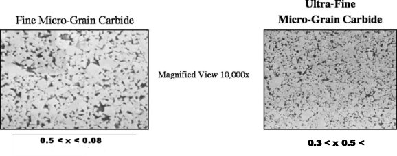
Figure 1: It is critical to note differences between carbide end mills for machining and carbide end mills for HSM. The most notable indicator of a quality substrate is grain size. Typically, the smaller the grain size, the better suited the tool is for HSM applications.
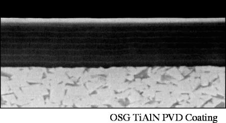
Figure 2: TiA1N PVD Coating-tests have shown that multilayered coatings are best for HSM applications.
When the phrase 'high-speed machining' (HSM) is mentioned, what is the first thing that comes to mind? In most cases, one might envision some sort of HSM center capable of high-accuracy milling at high spindle speeds and feedrates. This perception of HSM is not wrong, as the machine tool is the largest and most critical component in HSM applications. However, this intense focus on the machine tool can often shift our attention away from the other key components in the HSM process.
To be truly successful in HSM, it is critical first to recognize all of the key components and briefly understand the importance of each. They are:


- Programming
- Machine communications
- Control systems technology
- Machine tool
- Tooling
- Workpiece
Programming
This component refers to the programmers and their available options. Clearly, the software (CAD/CAM) available to the user dictates many of the programming variables from which they can choose. While an excellent software package will create various avenues to machining a part, poor software can limit machining options drastically and prevent the programmers from getting the most out of their machine and tooling. Material entry methods, toolpath generation and surface tolerance all are fundamental concepts involved in this component of HSM. The power of the software dictates how each of these fundamentals can be applied to the machining process. For example, many CAM packages allow the user to program helical engagement as a method of material entry. However, while some systems create a helical path using true arcs and radii, others simply follow straight-line moves that do not maintain consistent arcs as the tool cycles down into the part. This results in diminished tool life.
Other nonsoftware programming issues that often exist have everything to do with the programmers. In an industry in which trends and concepts often come and go, it is extremely easy to get lost in the seemingly endless pool of machining techniques used to enhance production. The following is a brief list of a few programming tips recommended to ensure the best machining results. They illustrate how just a few oversights could lead to poor productivity, even with the most advanced machine tool.
Programming Tips
- Using air blow when machining die steels such as D-2, H-13, P-20 etc., helps prevent thermal cycling by allowing the heat generated from the cut to leave with the chip. Introducing flood coolant to the machining process will result in the heat being induced back into the part and the tool. The heat causes the carbide tool to crack and thus, decreases tool life and tool performance. Using air blow also allows the operator to predict tool failure before a crash ever occurs. Prior to tool failure, changes in the color of the chip and tool can be noted, and tools can be replaced prior to any failure. As a result, tool life is predictable and the operator essentially can leave the machine unattended until it is time to change the tool again. Flood liquid coolant makes identifying what is referred to as the halo glow impossible. As a result, tool failure cannot be predicted using this coolant method. Lastly, most carbide tools for HSM should be coated with titanium-aluminum-nitride (TiAlN). This coating excels at higher temperatures due to the formation of aluminum oxide on the outside of the tool. The aluminum oxide, which is more prevalent in applications with consistent temperatures, provides added hardness and lubricity to the cutting edge.
- Use mist coolant for all applications with small-diameter tools, approximately 1/8-inch diameters and smaller. Mist coolant will extend tool life and improve surface finish quality. It also provides added lubricity to small diameter tools, while still allowing the heat to evacuate with the chip.
- To achieve better surfaces for finishing operations, adjust the finishing radial step-over so that it is equal to the chip load per tooth of the given end mill. By maintaining this equal relationship, the finish is the same in both directions.
- Use helical engagement as the material entry method in materials above 40 HRC. Helical engagement does not leave behind a slot like the linear ramping method. By eliminating the slot, the tool is no longer subjected to an interrupted cut and can maintain more consistent tool deflection, which is critical for tool life in harder die steels.
- When applicable, use trochoidal milling for roughing applications. This method of machining dramatically improves tool life. Heat is reduced as the cutting edge is only engaged for 5 percent of the tool's rotation versus 50 percent with conventional milling toolpaths. This method also improves metal removal rates because higher feedrates are maintained more consistently.
- Use the tools with the shortest overall lengths and flutes possible. For hard milling, shorter means more rigidity and longer tool life.
- Always plan for the next tool. Finish stock plus the added cusps from the previous tool, must both be considered to ensure that the next tool is able to run fast without exceeding its maximum depth of cut and ensuring the best possible surface finish.
- Take the guesswork out of programming speeds and feeds by getting the necessary information from the cutting tool manufacturer.
Machine Communication
This component refers to the manner in which information is processed and transmitted from the PC to the machine tool. The constant input of G-Code to the machine tool requires several systems to work together to process and interpret data into a control, which commands the actual mechanisms within the machine. The performance of these systems relies heavily on a good marriage between the PC and the machine tool. Responsibility for this integral relationship falls upon both the customer and the machine tool builder. The ease with which data flows to the machine tool and is processed has a tremendous effect on how efficiently and smoothly material is removed. The bottom line is that it is critical to feed the program to the machine faster than it is being used.
Control System Technology
This component refers to the dedicated CPUs, servo controls and motion control software incorporated into the actual machine tool. Typically, machines for HSM are equipped with two processors: one processor handles the day-to-day operations of the machine while the other is used to crunch numbers (G-Code). The capability of these controls depends on the individual machine tool manufacturer. High servo control mechanisms and look-ahead software are just two key essential variables necessary to be successful in HSM applications. Machines that feed up to 800 ipm are not necessarily equipped for HSM as they still require the appropriate systems and servos to control movement smoothly and accurately. The control dictates how fast the machine will actually run. Older machines equipped with the right control can be more productive than a newer machine with higher available feed rates.
Machine Tool
This component refers to the machine tool as a physical entity. The most important characteristics of any machine tool are precision and rigidity. The rigidity of the machine is determined by its design; therefore, it is crucial to operate on a machine that is designed specifically for HSM. Spindle bearings, guide ways and machine tool bases are all features that affect rigidity and precision.
Tooling
This component includes both the toolholders and the cutting tools where certain standards must be taken into account in order to be successful in HSM applications. The specified standards pertain to balance, concentricity and spindle connections.
Balance
Every expert in the die/mold industry has his or her own definition for HSM. As a general guideline HSM can be defined at 8,000 rpms or more at 100 ipm or faster. While there are many exceptions to this definition, the basis for this explanation deals directly with an issue of balance. Balance dictates how evenly weight is distributed to prevent centrifugal forces from causing excessive vibration. Repeated machining tests have shown that balance is critical above 8,000 rpm. Unbalanced tooling above this speed will cause excessive vibration diminishing spindle life, decrease quality in surface finish and reduce tool life as much as 35 percent. In fact, doubling spindle speed increases the force from unbalance by four times. Tripling the speed will increase the force from unbalance by nine times. In other words, if $100,000 were spent on tooling, $35,000 would be virtually thrown away by running unbalanced tooling. For these reasons, all toolholder assemblies should be balanced to the ISO g2.5 balance specification. It is important to make sure that this specification is adhered to the individual's maximum spindle speed capacity. In other words, any holder can be declared balanced if no corresponding spindle speed is called out along with it. The question to ask is not 'Is it balanced?' but rather, 'To what speed is the holder balanced?'
Concentricity
Concentricity and balance go hand-in-hand; however, they do not refer to the same thing. Concentricity measures how closely the toolholder aligns the tool to the centerline of the spindle. A lack of concentricity, when one tooth is taking a bigger bite than the other, is commonly referred to as runout. Runout at a lower speed is not critical, as the cutting load in conventional machining is so great that vibration is inconsequential. In high-speed applications, where lighter depths-of-cut are being used, runout will lead to excessive chatter and uneven tool wear. For example, most coatings range in thickness from three to six microns, or roughly a thickness of 0.0003 inch. With this in mind, it is easier to understand how even 0.0005 inch of runout can lead to premature tool failure.
Taper Tolerances
One of the most important relationships in the HSM process is the interface between the spindle and the toolholder. Large variances in fit between the toolholder and spindle socket will lead to fretting, which is seen by the discolored ring around many toolholder shanks in shops around the world. This commonly accepted ring is a result of vibration in the spindle. While it is impossible to achieve a perfect fit where no fretting occurs, it is very feasible to reduce the degree to which it happens. Therefore, a maximum taper tolerance of AT3 is recommended. The AT tolerance simply dictates a specific tolerance to which the holder and spindle must be held within. The majority of machine spindles are held to an AT2 tolerance, while the majority of holder's range from AT4 to AT5 taper tolerances. An important fact to keep in mind is that AT tolerances are cumulative, thus a machine tool with a tolerance of AT2 plus a holder with an AT tolerance of AT4, at maximum material condition, can have a tolerance as large as AT6. For this reason, it is critical to have a holder system that has the tightest taper tolerance possible.
| Chart 1: Cutting tool characteristics such as gripping power, reach, runout, balance repeatability and rigidity for every holder style is important. | |||||
| Runout | Rigidity | Balance | Cost | Comments | |
| Side Lock | Poor | Good | Poor | Low | Not for HSM |
| Collet Type | 10 microns | Good | Fair | Normal | Good beginning to HSM |
| Hydraulic | 5 microns | Fair | Good | High | Good run out, grip can cause problems |
| Mill Chuck | 10 microns | Excellent | Fair | Normal | Great rigidity, poor reach |
| Shrink Fit | 4 microns | Excellent | Excellent | High | Ideal for HSM |
Individual characteristics of various style holders also are important to be successful in HSM. Every holder has advantages and disadvantages, which can determine if the holder is well suited for a particular application. Observing characteristics such as gripping power, reach, runout, balance repeatability and rigidity for every holder style is important (see Chart 1).
Workpiece
This component refers to the actual material being machined along with the fixturing used to hold it. The machineability of every material is different; therefore, it is important to define the machining characteristics of the work to correctly apply the variables for all of the other HSM components. Quality of fixturing affects rigidity as it contacts the part directly and is the primary device used in preventing vibration. Furthermore, the fixturing also can present obvious physical limitations in terms of spindle movement in the X-, Y- and Z-axes. These limitations must be accounted for in the HSM programming component.
Cutting Tools
The proper holder maintained under all of the correct standards is still only as good as the cutting tool it contains. A quality tool is determined by three primary factors:
1. Materials (substrates)
2. Geometry
3. Coatings
Materials
The best designs and coatings in the world are of little value if they are not applied to the appropriate substrates. Using an end mill with a subpar substrate is like using a front door made from cardboard on a new house. From a distance it looks the same, but a closer look will reveal the obvious flaws that make it unsuitable for its intended purpose.
| Carbide Grain Classification | Grain Size [microns] |
| Fine Micro-grain Carbide | 1.0 ~ 1.3 |
| Extra-fine Micro-grain Carbide | 0.5 ~ 0.9 |
| Ultra-fine Micro-grain Carbide | 0.3 ~ 0.5 |
| Nano-series Micro-grain Carbide | 0.1 ~ 0.3 |
| Chart 2: The smaller the grain size, the better suited the tool is for HSM applications. For HSM, a grain size of 0.5 microns or less is recommended. | |
In today's fiercely competitive die/mold industry, it is critical to note the differences between carbide end mills for machining and carbide end mills for HSM. The most notable indicator of a quality substrate is grain size. Typically, the smaller the grain size, the better suited the tool is for HSM applications (see Chart 2 and Figure 1). For HSM, a grain size of 0.5 microns or less is recommended.
There are further elements that still dictate substantial differences even when grain size is equal. These characteristics are hardness and transverse rupture strength (TRS). TRS is a measurement of how much force (N/mm) can be applied radially to the substrate before it fractures. Hardness and TRS are controlled by the cobalt percentage within the given substrate. Higher cobalt percentages dictate a lower hardness and higher TRS, while a lower cobalt percentage dictates the opposite. For roughing applications, when radial forces are the greatest, more TRS is desired, hence a greater cobalt percentage. Tools designed and suited for roughing applications should sacrifice hardness by increasing cobalt percentages to achieve more TRS. The inherent cost to manufacture such carbides is not cheap when compared to regular fine micrograin carbide. Aside from the time and energy to produce a smaller grain size, other measures are taken to actually control the amount of molecular bonds between the carbide and cobalt particles. The ability to control the size of the cobalt and the number of bonds is another fundamental difference between a good substrate and a premium substrate. Since this difference is not notable to the naked eye, it is often deemed an unnecessary expense to the end user. The result of such an oversight is more cost and less profit.
Geometry
The concept of hard milling and/or HSM is still a relatively new concept. The technology needed to facilitate these new methods has only been designed in the last six to seven years. In examining the market, it is clear that tools manufactured ten and fifteen years ago for the conventional machining will not work in unison with the newer technology. Cutting geometry needs to be tailored for high-speed and feed applications where greater cutting forces and more heat are common. The advancement of machine tool and cutting tool technology has always gone hand-in-hand. The current advent of new machine tool technology has made it even more important for new operators to use tooling designed for these machines.
Three important characteristics every tool for HSM should have are accuracy, rigidity and longevity. In the die/mold industry, a synonym for accuracy is radius tolerance. The tolerance of any ball mill is critical if a moldmaker wants to avoid hours of benching time. Imagine machining a complex cavity mold, such as a bottle-bottom mold, using a 1/4-inch ball end mill that really measures 0.248 inch over the diameter. The amount of rework required to bench the cavity could very easily be the difference between a profit and a loss.
Other critical tolerances include the shank diameter. Shrink fit tooling, which is ideal for HSM applications, requires tools with h6 tolerance shanks. Not only must the shank maintain an h6 tolerance, but also true roundness as well. Roundness and diameter tolerance are two separate quality standards, and if they are not met, it can lead to the tool becoming permanently lodged inside the shrink fit holder. The bottom line is that the additional cost of buying an accurate tool is nothing compared to labor costs of added benching time and/or scrapped tooling.
The key feature of the cutting tool that dictates rigidity is the core diameter. The machining requirements set forth by the principles of HSM, place heavy emphasis on the tool and its ability to withstand axial and radial forces. Conventional end mills incorporate a standard core diameter thickness of approximately 50 percent of the tool's diameter. The core diameter is directly proportionate with the gullet depth of the flutes. This design is good for standard milling operations in carbon steels, but it is not rigid enough for high-speed applications in die steels such as D2 and H13. End mills for the die/mold applications should use a shallower gullet to sustain a thicker core diameter. HSM methods incorporate depths-of-cut that do not exceed any more than 10 percent of the tool's diameter. As a result, far less chip room is needed in comparison to conventional machining methods; hence, gullet depth can be sacrificed for a thicker core diameter.
Coatings
The nature of HSM generates less heat when compared to conventional machining, but the temperatures in the cut also are more constant. Therefore, more advanced physical vapor deposition (PVD) coatings are needed to sustain the cutting edge while it is engaged in the material. Standard coatings such as titanium-nitride (TiN), titanium carbon-nitride (TiCN) and monolayered titanium aluminum-nitride (TiAlN) have been acceptable for most machining practices. However, HSM methods require much more out of the coatings and tools to sustain acceptable tool life.
Similar to that of carbide substrates, tool coatings often look similar to the naked eye, but differ drastically when placed under the microscope. In fact, the amount of variations on TiAlN alone is almost too vast to count as new versions are hitting the market monthly. Like carbide substrates, the process is what differentiates one coating from the next. In fact, the process is deemed so important that some manufactures have patented their processes in order to prevent them from being duplicated by their competition.
From a machining aspect, tests have shown that multilayered coatings are best for HSM applications (see Figure 2). Multi-layered coatings, combined with other proprietary elements within each layer, prevent chips in the coating from penetrating all the way to the surface of the substrate. Instead, they deflect to the next layer, thus extending tool life significantly over that of regular mono-layered PVD coatings.
Bottom Line
A common misconception regarding HSM is that the machine tool is the most costly investment in the HSM process. However, over the entire life of the machine tool, the amount of money spent on cutting tools will far exceed that of the machine. With this in mind, it is essential to use high-quality tooling to truly maximize cost savings and profit margins.
Premium cutting tools use stronger substrates, specifically-tailored geometry and more efficient coatings that improve tool life and surface finish. Higher quality standards dictate a higher initial investment on the part of the end user, but the trade off to the moldmaker is dramatically reduced benching time, faster cycle times and repeatable quality that allows operators to leave machines running unattended with total confidence.
'The idea of trying to cut tooling costs is a false economy.1 The net worth of the tool pales in comparison to standard production costs. So often the focus is put on initial cost savings (tooling), when the emphasis should be on long-term savings (production), as this is where companies will see the most monetary return. Therefore, if one can minimize production costs by increasing initial tooling investments, they will take home more profits at the end of the day by improving productivity.
References
1Greg Bakker, Seco Tools, Technical Manager - Manufacturers' Monthly.


Related Content

How to Eliminate Chatter
Here are techniques commonly used to combat chatter and guidelines to establish a foundation for optimizing the moldmaking process.
Read More
Maintaining a Wire EDM Machine
To achieve the ultimate capability and level of productivity from your wire EDM on a consistent, repeatable and reliable basis, regular maintenance is a required task.
Read More
Laser Welding Versus Micro Welding
The latest battle in finely detailed restoration/repair of mold materials.
Read More
Machining Center Spindles: What You Need to Know
Why and how to research spindle technology before purchasing a machining center.
Read MoreRead Next

How to Choose the Right Tool Coating for Your Machining Application
Selection criteria and common coating attributes for PVD, CVD and other common coatings.
Read More
How to Use Strategic Planning Tools, Data to Manage the Human Side of Business
Q&A with Marion Wells, MMT EAB member and founder of Human Asset Management.
Read More
Reasons to Use Fiber Lasers for Mold Cleaning
Fiber lasers offer a simplicity, speed, control and portability, minimizing mold cleaning risks.
Read More