
A Specialized Mold Design Strategy
Solving complex mold design challenges with specialized CAD software.


Completed fixed half of games controller mold.
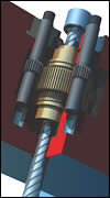
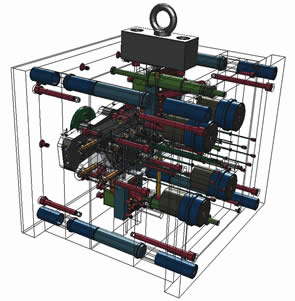
Sectioned view through complex screwed ejector system. Images courtesy of Delcam, Inc.
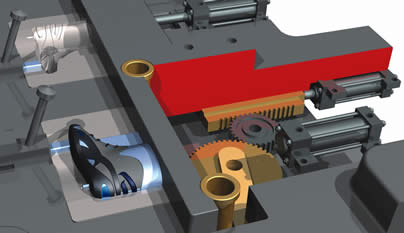
Actuator-driven slide detail.
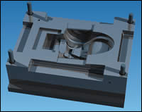
Completed fixed half of mold for vacuum cleaner cover.
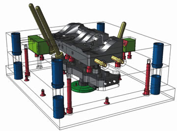
Completed tool ready for manufacture.
|
Throughout the past 25 years the plastics industry has grown almost faster than any other. Plastic prod-ucts fill our homes, our offices, our cars, our whole world; yet, seldom do we sit back and think how these products are made, or how those manufacturing pro-cesses can be improved, unless it is our business.
A Complex ChallengeWhen plastics were first gaining popularity, parts were simple. Most products were designed on a drawing board, so it was natural that the tooling was designed that way as well. All that was needed was a drawing board, a box of pens, a ruler, compasses, and a razor blade for when things went wrong or the design changed. Of course, the tool designer also needed a high degree of skill, and considerable patience for doing repetitive actions, such as drawing ejector pin holes. The introduction of 2-D CAD systems in the 1970s improved mold design in two key ways: (1) routine, repetitive tasks were massively simplified by the ability to copy geometry from one area of the drawing to another. This was made even easier by the introduction of symbols, allowing complicated sub-assemblies to be stored in a library and added to the drawing at the click of a mouse; and, (2) making modifications to a design also was simplified, as areas of the drawing could be deleted, moved, re-trimmed or stretched to accommodate the change. But still the biggest issue was successfully and completely defining a complex 3-D form using 2-D drawings. As CAD has evolved into 3-D the complexity of plastic molded parts has increased. Modern plastic products seek to be increasingly creative in terms of form, while being more functional and durable. For the mold designer, these new forms have forced a requirement for CAD systems to be able to accurately reproduce complex shapes, not just for the visible parts of the product, but especially for the functional parts of the mold, such as parting surfaces. While the modern generation of CAD systems can cope with this increased complexity, much of the mold designer’s work is still routine and mundane. Consider placing a series of ejector pins into a mold cavity block. Each pin must be placed individually, complete with its corresponding clearance hole and then trimmed to length. Even allowing for the fact that computers can do this type of operation very efficiently, the mold designer will still be spending too much time and effort on tedious tasks, and not enough on making sure the design is perfect.
A Special SolutionIn recent years a new generation of specialized mold design CAD systems has begun to appear. By automating the tedious parts of the mold design process, specialized CAD allows the mold designer to spend more time being creative with the tool design itself, helping to produce better quality molds. The upshot of this is better molds and parts, faster. Specialized mold design software allows the tool designer to quickly and accurately divide a complex component into cavity and core halves, complete with all of the necessary split and run-off surfaces. Fast and intuitive tools allow the mold designer to isolate and extract complex sliding core mechanisms directly from the initial 3-D design, and then animate them to check for fit, function and clearances. Once the main mold parts—such as cavities, cores, slides and mold locks—have been defined, the completed mold stack is only a few clicks away. Standard and user-defined components—including complex mechanisms, such as hot runners, staged ejectors, lifters, etc.—can be added to the basic stack at any time, each with associated holes and pockets for fitting. For mold shops that still require paper drawings, automated drafting creates GA and a detailed sheet of any components or plates with a single click. Automated bills-of-material give instant access to online ordering systems for purchasing the standard plates and components, guaranteeing that the entire build is ready on time, every time. The end result is a complete, fully detailed and accurate 3-D model of the mold tool, and it is here that the real benefits of the process become apparent. Although the initial design can in some instances take longer than using traditional methods, manufacturing from this point forward is mostly automatic. The 3-D model of a single plate, for example, is not simply a traditional CAD solid; it is a library of manufacturing data, allowing machining of all the holes and pockets to become a one-click operation when used in conjunction with a CAM system. Each hole or pocket is not just a geometric entity, but instead holds complete details of its function and how it is to be machined. User-defined rules are automatically applied as each plate or component is machined, creating all necessary toolpaths quickly and accurately. For complex cavities, cores and split surfaces, full 3-D CAM allows perfect reproduction in tool steel using up to five-axis simultaneous control for fine surface finish.
Productivity GainsThe productivity gains to be made using these new methods are significant, with customers typically reporting time savings of between 30 and 40 percent for complex projects. At the same time, product quality is significantly improved as a direct result of the designers spending more time in making sure that the design is the best possible. |


Related Content

How to Select a Mold Temperature Controller
White paper shares how cooling channel analysis, which collects maximum pressure drop, total flow rate and heat dissipation, eases the performance evaluation of mold temperature controllers.
Read More
Tolerancing in Mold Design, Part 2: Using GD&T to Address Conventional Tolerancing Issues
Mold designers can achieve a single interpretation of workpiece functionality when following the American Society of Mechanical Engineers Geometric Dimensioning and Tolerancing standard.
Read More
CAM Automation Increases Mold Production, Quality
Mold builder switches CAM software package after 20 years to take advantage of innovative programming strategies that reduce mold machining programming and processing times.
Read More
OEE Monitoring System Addresses Root Cause of Machine Downtime
Unique sensor and patent-pending algorithm of the Amper machine analytics system measures current draw to quickly and inexpensively inform manufacturers which machines are down and why.
Read MoreRead Next

Moving Mold Design From 2-D to 3-D
Moving to 3-D mold design can provide a very effective way of improving competitiveness and helping companies win more business.
Read More
Crash Test Genius
Toolpath verification software has evolved to permit simulation of the entire machining system.
Read More
CAD/CAM Does Double Duty
CAD/CAM software makes molds faster and helps trim parts.
Read More